Saturday, October 31, 2020

Binary clock (Part 3)

Introduction

I was going to name this post "binary clock and practical examples of over-engineering" but perhaps this isn't exactly over-engineering. Over-engineering implies that something simple is done in a very complicated manner. Here I'm going to describe some simple implementations for rather simple ideas. It's just that the ideas are either very genius or very stupid. Don't really know which yet. Perhaps it's both?

Apparently there's another meaning for the word over-engineering. It also means designing a product that is more robust or has more features than necessary and I guess the second part applies here. So I guess this is over-engineering after all. Anyways, more features!

(more)

Code

As previously, these new features require only new code. Well, the brightness correction would require some hardware modifications, but I'll leave that for another time.

Low Battery Text

I spent an awful lot of time to come up with a way to indicate the low battery situation. I mean, the display could just blink, or the picture could be inverted or even rotated randomly, but none of those feel intuitive to indicate the low battery situation. There are also so few pixels that there couldn't really be a picture of a battery. Later I realised that there are still enough pixels to show a scrolling text "battery low". For this I didn't really bother making code for forming text on the display so I simply hard-coded the picture with said text. This picture is then scrolled on the display and is more or less comprehensible to the user. Below is a picture that I've used to hard-code the text into the program.

Picture used for the scrolling text to indicate low battery situation

The code required for this feature is relatively simple. The first part is to store the image that will be scrolled. For simplicity's sake I've decided to store it in such a way that the 4 LSBs of each byte represent one row of the picture shown above and the MSBs are unused. Below is the beginning of the picture as it is in the code. Try to see the connection between the code and the letter b in the picture above. The picture (in the code) is both mirrored (vertically) and rotated (90 degrees CW) because that's how the display is oriented. The rotation and mirroring could be done in software but I would say that that's completely overkill for this kind of purpose. The array should also be 4 rows bigger than the picture, so that the display is completely empty before and after the scrolling text.

const __flash uint8_t low_bat_text[] = {
   0, 0, 0, 0,
   0b1111,
   0b0101,
   0b0010,
   0b0000,
   // ...
   0, 0, 0, 0
};

The code responsible for displaying the given picture is also quite simple. I've added the low battery situation as a state to the device. The low battery detection explained in part 2 sets the current state to LOWBAT_ST which enables the code below. After that the low_bat_display_counter represents the position in the scrolling picture and also resets the state back to TIME_ST after the whole picture has done scrolling. The picture is also transferred to the display_bits variable so that there's always 4 rows in the picture and the values from the low_bat_text are shifted appropriately. The MSBs are zero, so they don't require any kind of masking and the resulting code is very simple. Note that the device should actually return to the previous state which might be something else than TIME_ST.

if(low_bat_display_counter < sizeof(low_bat_text) - 4) {
   display_bits = (low_bat_text[low_bat_display_counter] << 12) |
   
               (low_bat_text[low_bat_display_counter+1] << 8) |
                  (low_bat_text[low_bat_display_counter+2] << 4) |
                  (low_bat_text[low_bat_display_counter+3] << 0);
   low_bat_display_counter++;
} else {
   display_bits = 0;
   low_bat_display_counter = 0;
   current_st = TIME_ST;
}

ps. I've mentioned the rotating display and would also like to mention that at some point I had a round shaped clock from Philips that had a rotating display. I mean the display would not rotate, only the picture. It was quite a funny device since the display was in no way symmetrical, but still it could rotate to 0, 90, 180 or  270 degrees and would still be readable. The funniest part was the sensor which was responsible for the detection of the rotation. It was actually a gold plated metal ball in a plastic cage that would roll freely and short different gold plated metal bars depending on the orientation. Needless to say, the sensor didn't work very well.. it started failing relatively soon. The clock would still work but it would require a lot of shaking to change the orientation of the display. Perhaps I could take a picture of that sensor if I still have the clock and share it here later on.

Temperature Compensation

As mentioned earlier, the temperature measurement of the device is absolutely useless without any modifications. The measured temperature is at least one degree higher than the ambient temperature. I suppose this is because the device heats up even with reasonably low brightness. Originally I just thought to leave it as is, but then I started to think whether something can be done about it. I have to admit that I have studied something related to this but I've effectively forgotten this topic. However after some searching I found a very simple equation (the only equation on the page) that could be used here. In this case, the junction temperature is the measured one, the power is the power used by the whole device, the ambient temperature is what we want to be able to read and the thermal resistance is something that I'm just going to calculate/guess. This is in no way accurate, but it might make the temperature sensor even remotely useful. At least the equation is linear, and all linear things are good.

The first issue here is to measure the (relatively static) current consumption of the microcontroller. After that the current consumption of the LEDs should be calculated including their current consumption in idle state (with the light switched off). After measuring these values the device should be able to calculate the theoretical current consumption based on the LED states. The last part in this equation is to calculate the thermal resistance. This can be done simply by reading the measured temperature and comparing it to the ambient temperature measured with any other device. So the equation is:

T_a = T_s - P * R_t,

where T_a is ambient temperature, T_s is the temperature measured by the sensor, P is the power consumption and R_t is the thermal resistance of the system. I've measured that the static current consumption of the device (microcontroller and LEDs) is around 14.5 mA and dynamic current consumption is around 40.5 mA when a single LED is on full brightness. I've also measured that current consumption of each colour is quite equal. Calculating the total current consumption of the device then only requires sum of the colour intensities of each led and the following equation:

I_tot = 14.5 mA + 40.5 * sum / (255*3)

The last missing part is the thermal resistance. Originally I thought I would make one measurement and compare it against some reference. Then I remembered that I don't have a proper reference and also the effect is linear, so I can just make multiple measurements and compare them against each other. For this purpose I simply made a mode where all the pixels are enabled, but still the colour and the brightness can be set manually. I then set the device to each possible brightness, let it stabilise for a while and take the temperature measurement for each respective brightness. After that I plotted all the data in excel as shown in the picture below. I should have used any other software (I would prefer Gnuplot) but excel was much quicker since there's not so many data-points and this is not very scientific in any case..

Measured temperature against power consumption

From this we can conclude that the temperature at the moment of measurements was 24.6 C (the LP value in the table) and that the thermal resistance is 12.8 mOhm (I suppose). The T_real row represents the ambient temperature calculated from the measured temperature using these exact values. As we can see, it's not really foolproof and I really don't believe the temperature in this room was 24.6 C at the time of taking these measurements but I suppose it's fine. At least the graph looks linear as the equation suggests.

Following this measurement I implemented a correction factor in the code. The correction requires first calculating the current consumption and then the actual temperature correction factor. The example code is shown below. Note the unit conversions so that the calculations don't overflow.

#define THERMAL_RESISTANCE 128 // Unit is 10^-4

// Calculate the current consumption (in units of 0.1 mA)
uint16_t led_sum = 0;
for (uint8_t i = 0; i < LED_COUNT; i++)
   led_sum += colors[i].red + colors[i].green + colors[i].blue;
current_consumption = 145 + (uint32_t) (led_sum) * 405 / (3*256);

// Make adjustment to the measured temperature
// Temperature unit 0.01 C, current unit 0.1 mA, resistance unit 0.0001
shtc3_temperature -= (uint32_t) (current_consumption) * 5 * THERMAL_RESISTANCE / 1000;

One issue here is that the current consumption might fluctuate quite a lot. Imagine the temperature change from 27.77 degrees to 28. The first one requires ten LEDs to be on and the second one only two. For this purpose I thought about adding some averaging here, but I suppose the (already implemented) temperature averaging will be sufficient for this purpose. The correction of the temperature should of course be done before the averaging in this case and that's exactly how I've done it. Now the next question is whether this makes any sense, since the only reasonable brightness settings are a few lowest ones. But we can see from the graph and the calculations that even the lowest brightness setting does indeed increase the measured temperature by one degree and that's quite a lot. After this adjustment I've found that the device more or less agrees on the temperature with the other devices that I have here. So I guess that's good enough.

Note: The calculations above assume pretty much that the power used by the device is spread evenly around the PCB. That is probably not the case, but I don't really know to which extent. Similarly this adjustment assumes that the temperature of the device has stabilised. The device will obviously show erroneous temperature for a while after just being switched on. I could of course measure whether the first issue is really an issue and then more maths can be added to mitigate this problem. The other issue however cannot really be solved. Of course the device should always have power so it could just keep track of the current consumption also in sleep mode. But that's just.. over-engineering to such an extent where even I don't want to go right now. Also the temperature sensor is not connected to the backup battery, so it cannot be used with this hardware. The only viable solution in my point is to measure the slope of the temperature changes and blink the display to indicate to the user that the temperature measurement might show bogus values at the moment. After the temperature stabilises the display should stop blinking to indicate that the displayed value should represent the actual temperature.

ps. Someone might remember that there's also the relative humidity measurement in addition to the temperature measurement. Originally I thought that I shall also adjust that value. However there are two issues. First of all, the relation of relative humidity to the temperature is so complicated that I've just decided not to touch that topic. Also I'm not really sure whether the value of the relative humidity measurement should be adjusted.. I don't have a good reference for measuring the relative humidity, but the best thing I have, shows very similar results without any adjustments. So perhaps it's good as it is. I don't know much about the relative humidity and I don't really want to learn right now. After all this is just a fun project and I already have better devices for measuring relative humidity.

Brightness Compensation

The Nyan Cat display more explained in the second part has one major issue. The idea of that mode is to gradually change the colour of each pixel on the display, without changing the intensity of the light. However the intensity of the light does change even if the software is supposed to only change the colour. One simple explanation is that the intensity of each colour is different. That could be fixed with a simple correction factor (multiplier for each colour). The maximum intensities of the different colours of the WS2812B LED are actually specified in the datasheet. This way the correction factor can be added to the code.

Wavelengths and intensities of different colours in WS2812B LED

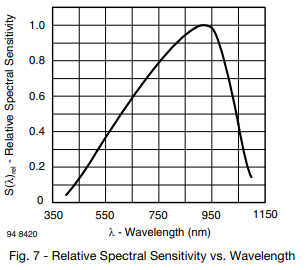
This however doesn't seem to be the only issue. The intensity seems to change also between colours. This means that the intensity doesn't change linearly to the values sent to the LED. Unfortunately this non-linearity is not documented in the datasheet. I almost gave up regarding this issue, but then I had an epiphany. The non-linearity could simply be measured empirically and compensated by using a hard-coded LUT (Look Up Table). Moreover the measurements could be done with the photo-diode that is actually already on the device.. The device should just be set to enable all the LEDs, get a reading using the photo-diode and output it via the serial line. This should then be looped over all the LED intensities and all the colours in case the sensor reacts differently to a specific colour. Actually the sensor does have different sensitivity for different wavelengths as can be seen in the picture below.

For the purpose of this measurement, I've also set a mirror at a suitable distance from the LEDs to reflect the light back to the sensor. I've also covered this setup with something dark to avoid disturbing the measurement with ambient light. Below is the result that I got. The absolute value of the y axis is quite meaningless here, were only comparing the different colours and looking at the linearity of the graph. The graph does look very much linear except for the leftmost part. And perhaps the leftmost part is the most important part in this project since the LEDs are so bright that they will hurt your eyes on any higher brightness setting. Right about here I realized that I could have simply made a google search regarding the LED linearity with PWM output. Also there are some small "holes" in the measured data and I have absolutely no idea what are those.

Light intensities of different colours at different PWM values

Let's think about this graph a bit. We know that the PWM output is by definition linear. The amount of the energy transferred is directly proportional to the pulse width. That is of course without taking the rest of the system into account. The rest of the system is the actual LED component here and it's kind of logical that it doesn't switch on immediately including any possible FET transistors involved. And this switching delay is what makes the PWM system nonlinear. Well at least according to this source, and at least to me it makes sense.

I tried to replicate this behaviour with some theoretical maths but that was just too much for me right now. Originally I wanted to delve a little bit deeper into this topic but honestly I really don't have the energy. The most important question is whether this non-linearity can be dealt with one way or another. And unfortunately at least I couldn't come up with anything. We need PWM values as low as 7 for sensible brightness of the display (especially with darker ambient light) and at that point we cannot really do any sensible dimming. So unfortunately the result will still stay nonlinear unless the LEDs are physically dimmed somehow, for example with some dark foil under the front plastic.

However we can at least try to balance the different colours using the datasheets and this measurement setup. The average intensities or RGB colours for the WS2812B are 405, 690 and 190 respectively. This means that we need to divide the PWM of the red value by 2 and the green by 3.5 so that they have the same intensities as the blue one. However before running the full measurement again, let's see how similar is the graph above to the theoretical values. The sensitivity of the BPW34 for respective wavelengths are approximately 0.65, 0.35 and 0.2. Let's just apply these to the intensities above so we get 263, 242 and ... 38. Well that doesn't look at all similar to the graph above. I suppose this is a good point to simply give up. This topic clearly requires more research and I'm not willing to do that right now.

Another good reason to give up at this point is because human eye reacts differently to different wavelengths. It means that the intensity written on the datasheet might not represent the intensity seen by a human eye. This would require even more adjustments and perhaps I will have to deal with this at some later point in some other incoming project. I do like colorful lights so I will most definitely have to think about this in the near future.

ps. Taking the intensity measurement didn't work so well at the first try. I didn't really understand why I was getting quite random results and I only understood it a few days later. The issue here is that there are 16 LEDs controlled by unsynchronized PWM.. It means that their PWM might drift randomly in respect to each other even if their pulse width is the same. I also checked the sensor voltage with an oscilloscope and the result was quite unintelligible as one might expect in this case. Unfortunately I don't have a screenshot of that and I've already disassembled the measurement setup, so I'm not going to provide a picture here.

Automagic Frequency Correction

In the second part I've described how to add a correction factor to a clock. It only requires a reference and a long enough measurement period. More specifically calculation of the correction factor requires two synchronisations to a known reference, time measure between these syncs and the time difference (to the reference) at the second sync. Then the user can calculate the correction factor and input it into the device. After that the user will also adjust the time as it should have drifted significantly to have any meaningful measurement.

Now someone might figure out that the device could calculate the correction factor by itself, since both values mentioned above can be calculated from the second sync. The rest is just maths, assuming that the user does both synchronisations correctly of course. Then we simply have to decide how the device should correct the time. Previously I've said that adjusting by one second in a specific time interval was not good. However it's not good only when the granularity of the interval selection is relatively large. Now that the user doesn't need to enter the value, it can easily be measured in seconds, which in turn makes it much more accurate. Of course the interval could be also set manually with the accuracy of one second but that's perhaps just .. too much.

This functionality would work as follows. First the time interval should be measured between two syncs, and this is already implemented. However this time interval should now be measured in seconds. Additionally it should calculate the time difference between the running time and the new set time. This will require some modifications to the previous code as I've decided to stop the clock while the time is being set. The difference itself is quite easy to calculate, first both time values should be converted to seconds and then simply subtracted. After that the interval between measurements should be divided by the time difference. This result will be the interval for time correction and the sign of the time difference will define whether one second will be added or subtracted from the time.

First things first. We need to solve the time stopping issue. To have the same effect and keep both values (running time and the one being adjusted), we can separate the active time and setting time. The timer would always keep running and update the active time. When the user wants to set the time, the active time would be copied to the setting time and and that will be displayed while the user is setting the time. When the device shall exit the time setting mode, first the difference between the setting time and active time should be calculated. After that the setting time should be copied to the active time, the timer counter should be cleared and the device should again display the active time.

The time interval measurement should be for example 32-bit wide unsigned variable and it should be incremented every second. This width will be enough for around 130 years so I guess that's enough. The time difference should then be calculated from the two timestamps (the active and setting times), that's the time at the sync and the time set by the user while syncing. The rest is a simple division and sign detection. I've decided to make all variables as signed to simplify the maths a bit.

// All values signed just for more simple maths
int32_t corr_conter = 0;
int32_t active_time = act.h * 3600 + act.min * 60 + act.sec;
int32_t setting_time = set.h * 3600 + set.min * 60 + set.sec;
int32_t corr_diff = (active_time - setting_time) % (24 * 3600);
// -> Replace with code shown below
int32_t corr_interval = abs(corr_counter / corr_diff);
int8_t corr_value = corr_diff < 0 ? 1 : -1;

There are, of course, a few things to note here. I suppose the first thing to note here is that the corr_diff might be equal to zero. That should technically be taken into account. Secondly this simple code would only work assuming there is no correction factor currently set. If there is already some kind of correction factor in place, it should be taken into account when calculating a new one. So in a way the code should revert the effect of the current correction factor to calculate the new one. Below is some example code.

// Revert the effect of existing correction factor
if(corr_value != 0) {
    corr_diff -= corr_value * (corr_diff/corr_interval);
}

// Leave the correction factor as is if there is no difference
if(corr_diff != 0) {
    corr_interval = abs(corr_counter / corr_diff);
    corr_value = corr_diff < 0 ? 1 : -1;
}

There is however one major issue here, which is perhaps the reason this kind of feature is not implemented in any commercial device. The issue is, of course, a possibility of user error. If we assume that the time is set incorrectly, the next sync will cause the device to calculate an erroneous correction factor. The next sync after that will also have the same effect because the previous one was the faulty sync. The fourth time will correct the issue if the time is set correctly. So in short, the device will require two proper syncs with any meaningful time difference between the device and the reference.

ps. Another issue not discussed here is DST (Daylight Saving Time). I'm sure everyone is familiar with that but nevertheless. This means that the time sync could have a difference of approximately one hour and of course any drift on top of that. I suppose that can be easily dealt with by simply detecting whether the difference is ~one hour and then adjusting for 3600 seconds which is one hour. For example if the difference is equal to 3607 seconds, the value used in calculations above should be 7 seconds. For this we need a simple piece of code, for example if the difference is more than 45 minutes and less than 75 minutes, subtract one hour to the difference. Similarly if the difference is bigger than smaller than -45 and bigger than -75, add one hour.

ps. ps. Obviously there might be something here that I haven't really thought of. For that reason it would be good to add some error checks, which would prevent the device from calculating some insane correction factor. However I would first just try it like this and see how it will go. What's the worst that can happen? :)

ps. ps. ps. This is starting to sound like I'm calling a cat. There is another very obvious issue here. When the device is started the first time, the clock is set to some time. And obviously this time should not be used for the first calculation. For that reason there should be some kind of time set bit that is set after the clock is synced the first time and only after that this correction should actually be enabled. As stated previously, it requires two proper syncs. So the startup time should not be used for the calculation.

Daylight Saving Time

Writing of this post happened to last so long that I actually had to adjust some clocks because of daylight saving time, including this device. After I realised that I have no less than 5 home made devices that didn't change to winter time automatically I realised that this clock could also be able to do it itself. For some reason it never occurred to me that this device could still have the date information even though it's not supposed to show it. It could be a hidden feature just like the correction factor things I explained in the previous part. For example at startup the date would be 0.1.2020 and if the user changes it to some meaningful date, it will enable the date calculation and automatic DST adjustment. The code for this feature is actually quite simple. I actually wrote it already some time ago, but apparently I forgot to add it to the latest of my devices. Update: this code was included in three devices of the four mentioned above, but the dst bit was set incorrectly. :)

// Daylight savings time
if(time.mday > 24 && time.wday == 6) {  // Last sunday of month
    // MARCH, 03:00 -> ++
    if(time.mon == 3 && 
time.hr == 3 && time.dst == 0) {
        time.dst = 1;
        time.hr++;
    }
    // OCTOBER, 04:00 -> --
    if(time.mon == 10 && 
time.hr == 4 && time.dst == 1) {
        time.dst = 0;
        time.hr--;
    }
}

The code should just have the information which month, day of month, weekday and the current time. Additionally there should be a dst bit so the device knows whether it make the specific adjustments. The dst bit is not really necessary when changing to summer time since one hour is added to the time and there can be no confusion, meaning that the time goes from 2:59 to 4:00. When changing to winter time however, the time goes from 3:59 to 3:00 and it's important to know whether it's "summer time" 3:00 or "winter time" 3:00, because otherwise the device will be stuck in a loop.

Speaking of dst bit and weekdays, I've never actually implemented calculation of these. It was either set by hand or received from the PC over a serial line. Now I thought about it and decided that the device could indeed calculate both of these by itself. The dst bit is a bit tricky to calculate, but it should be quite self explanatory compared to the code above. The idea is simply to check whether the date is between the last Sunday of March (3 o'clock) and last Sunday of October (4 o'clock). If it is, then the dst should be set to one. The weekday calculation is even more tricky. At least if the code below is considered. I've simply copied the code from here, which is in turn copied from here. I suppose it's worth checking out but I don't really recommend spending much time on it.

// Set the DST bit automagically
if(time->m < 3 || time->m > 10 || ((time->d - ((time->wd+1)%7) > 24) && ((time->m == 3 && time->hr < 3) || (time->m == 10 && time->hr > 4))))
    time->dst = 0;
else
    time->dst = 1;

// Set weekday automagically
int d = time->d, m = time->m, y = time->y;
time->wd = (d += m < 3 ? y-- : y - 2, 23*m/9 + d + 3 + y/4- y/100 + y/400)%7;

Automatic brightness

I've explained in the first part that the device has a light sensor that could be used for measuring the ambient light. I've also explained that it's facing the same direction as the LEDs and that it will most definitely pick up the light that is coming from the LEDs which will render the sensor absolutely useless. I've also used this to my advantage in this part but that was done with a mirror.

The main question right here is whether it is actually useless or not. The second question is how to evaluate that. For this I've set up the device to measure the voltage of the light sensor every 200 milliseconds and send it via serial line without any averaging or any other adjustments. I've set the reference voltage to 1.1 V because the measured voltage is quite small. After that I've assembled the "case" of the device and connected the serial cable with test clips to the test points, which required some skill. Then I simply set the device to a location where I've had it for a few months already and monitored the values seen on the serial line with different light setups and brightness settings.

This time of the year is not very convenient for this because there's hardly any light outside.. However I've concluded that in dark lighting the device will pick up almost no interference from it's own LEDs. Even with the maximum brightness, the maximum value measured by the ADC is 2 and it goes up to 4 if I put my hand in front of the display. However when I switch on my table lamp the value goes up to 10. The ceiling light however makes the ADC value go up to 4 as well as the sun did today even if it was quite dark in general. From this we could conclude that the self interference has a maximum value of 2 and the general lighting has values 4-10, which in my opinion makes this sensor actually useful!

Another less scientific way to investigate this is to have a flashlight with a relatively uniform light beam. This way the brightness of the light can be controlled simply by moving the flashlight closer to or further from the display. Now this is purely based on my personal feeling, but it really feels like the display is perfectly readable on lowest brightness when the ADC value is below 10. The next brightness level is then perfectly readable until around 30. At least when the used colour is red.

I have to say that I'm not very good at making "automatic brightness" features and I don't have much scientific background on this topic. I'm also not going to implement any such feature right now, but I can share some details how to get a decent result based on my earlier experience. I would recommend some kind of averaging of the measurement values and also a Schmitt trigger. For example in this case, the lowest brightness would be used when the ADC values are 0-7 and at 8 it would change to the next brightness. However when at the second brightness, it will stay there until the ADC value drops down to 4. This way the device will flicker much less in case there are small changes in the ambient light.

Results

The low battery text is working perfectly, the temperature compensation is working reasonably well and the brightness correction doesn't work at all. For obvious reasons I cannot really comment on the time correction code, since it might take some time before I see any results. However I had very good progress compared to the previous devices I've done. Lastly the brightness measurement is working quite nicely even though I thought it would be absolutely useless. The only thing that is worth showing here however is the low battery animation so here it is.

Final words

OMG it's finally done. It feels that I don't have enough friends to declare that IT'S FINALLY DONE so I'll just say it here. This has been quite a ride from the beginning til the end. I didn't really plan to do this much from the beginning. It was just supposed to be a simple clock with a few funny features. Well it's actually exactly that but it did take a lot of thinking and time. But again documenting own projects is good, so that at least (hopefully) I don't have to invent the same things over and over again. After all, many of the things described here can be reused in other projects.

I would say that this project is now finished even if I failed to implement some features. This reminds me of "Definition of Done" or DoD in short. I suppose DoD here is that I've implemented most of the things I was going to and even some that I wasn't going to. I have to say that I had a lot of fun and learned a lot of things and these two were the main objectives of this (mostly) useless device. Next I will do something more meaningful. Right now I will take a break however and read a book or something. Just kidding, I already have three new projects planned.

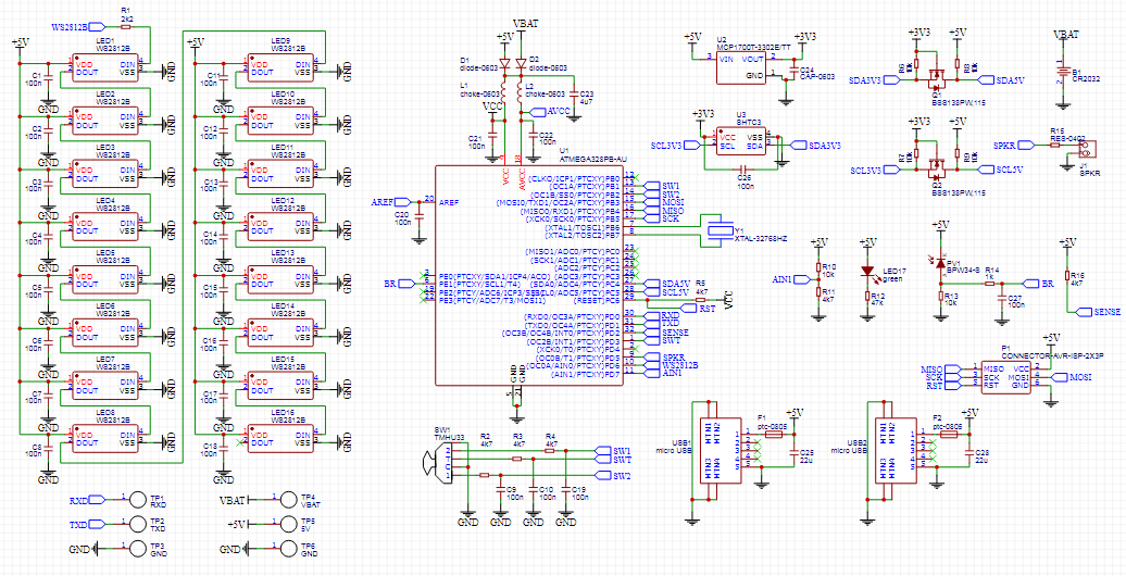
The EasyEDA project can be found here. Please note the errata in the schematic. I'm not going to fix the issues unless I make a new revision. I will also share the code in GitHub whenever I feel like or if anyone asks.

Thursday, October 15, 2020

Binary clock (Part 2)

Introduction

The hardware described in the first part of this instalment makes it possible to implement quite many interesting features as I've already tried to explain. Furthermore most of the features require very simple code so it would be a crime not to add more features to the device. Combining the features however tends to get messy, but I'll try to explain all the features and their necessity as simply as possible. 


Code

In the first part I've explained the basic clock function, how to update the display and how to read the input from the "lever and push action" thingy as well as the sleep mode. Here I'm going to explain some more basic clock features and some other things. Again all the register writes are pretty much specific to the used microcontroller, but all the other code should be quite universal.

Setting the Time

The clock part was already discussed previously, but there are a few details that are necessary to make a usable clock. First of all the user should be able to set the time. This was pretty much implemented in the first part. However the device should somehow indicate which value the user is adjusting (whether it's hours or minutes or anything else). I suppose the universal way of indicating that is simply by blinking the value that is being adjusted. The question is then what frequency and what duty cycle the blinking should have. For this I've simply checked the commercial devices that I happen to have and I suppose the fitting values are simply 1 Hz and 50%.

Implementing this in software is quite easy. First of all we should have the display update frequency faster or as fast as the blinking frequency. We should also have a counter to indicate when the value should be blinked. The last thing is to blank the respective part of the display (hours or minutes) whenever that value is being adjusted and the counter has reached some value. Below is a simple code example assuming the update interval is 200 ms and only for setting the time (hours and minutes). It's not exactly 1 Hz, but it's good enough. Instead of blanking the LEDs the device could also invert that part of the display, which would make the device look interesting and also quite psychedelic. :)

// Blink part of display when setting values
if(current_st == SETHR_ST && blink_counter >= 2)
  display_bits &= 0x00ff;
if(current_st == SETMIN_ST && blink_counter >= 2)
  display_bits &= 0xff00;
if(++blink_counter >= 4)
  blink_counter = 0;

Another issue that was not represented previously is that the user might want to set the time as precisely as possible (without any kind of automation). In my opinion a satisfactory result can be obtained with two actions. First the clock has to be stopped when the time is adjusted, so that the time doesn't change just as you're finishing the adjustment. Second the seconds should also be set. Setting seconds is usually done in a way, that the seconds can be zeroed by a press of a button. Or alternatively the seconds will be zeroed automatically when the hours and minutes have been set. These two features are quite easy to add to the current code. The code below represents a snippet of the button processing code shown in the first part. When entering the time setting state, the RTC timer is stopped, the timer counter is cleared and the seconds are also cleared. When exiting the time setting mode (after the hours and minutes have been set and the trigger key is pressed again) the timer is restarted.

if(*current_st == TIME_ST) {
   if(buttons == SWTL){ *current_st = SETHR_ST; TCCR2B = 0; TCNT2 = 0; time->sec = 0;}
} else if(*current_st == SETMIN_ST) {
   if(buttons == SWT){ *current_st = TIME_ST; TCCR2B = (1<<CS22)|(1<<CS21)|(1<<CS20);}
}

Clearing the timer counter is necessary above, since the smallest time step in this device is 8 seconds. If the value were not cleared, the time would technically be anything between 0 and 8 when the timer is restarted. It's also important to re-enable the timer if the current state is changed somewhere else, like for example in an automatic timeout as explained below.

Frequency Correction (theory)

I'll admit here that this is not my favourite topic, but it's something that has to be done and I'm trying my best here. This is not the first time I've been thinking about this, but this time I'm going to write down my thoughts. Also this topic is so long that I've split it in two parts. :)

Another thing that should be clear to anyone who has ever made a clock is that no clock crystal is 100% accurate. This means that the clock will most definitely drift in some direction. An obvious solution to this is to measure the actual frequency and make a correction factor for each device. However it's neither easy to (directly) measure the frequency nor make a correction to the frequency. The typical accuracy for a clock crystal is ±20 ppm (parts-per million). This means that the maximum error is 0.00002, which is ~0.6 Hz in case of the 32768 Hz clock crystal. I do not possess such tools that would allow me to measure that kind of inaccuracy. Also we cannot really compensate the frequency directly. The error is of course relative and we cannot really adjust for 0.00002 seconds or less every second (unless we use floating point maths but that would be simply stupid).

We can however adjust the time with any accuracy simply by adjusting over a period that is long enough for the units that we can use. For example with the maximum ±20 ppm error, the clock could drift by ~12 seconds in one week. We can simply measure this drift and add or subtract the respective amount of seconds once a week. For this we obviously need a reference and previously I've simply used time.is since it can show the time with large numbers. I don't know about the accuracy of that site, but it has been good enough for my purposes.

There are two things that are necessary to make this kind of adjustments. First we need to know how long the device has been running since the last sync. Previously I've been simply writing down the timestamp when updating the time and then calculating the duration manually. But this could of course be calculated in the device itself. Secondly we need to know the exact time of the device including seconds. The error in time value could be quite small in a short period, but the cumulative error over a few months can be very annoying. The idea here is that the user (including me) will not want to spend a lot of time for this kind of time adjustment, so we need to see the time drift as accurately as possible in a relatively short time period.

The details above could be demonstrated with the following calculation. If the clock drifts for, let's say, 2 minutes in 3 months, we can calculate that the drift is 120 seconds in ~7776000 seconds (depending on which months are in question). From this we can calculate that the error is ~15 ppm and we can compensate for that by adjusting the device by one second in exactly 18 hours.

Frequency correction (practice)

Let's start by measuring how long the device has been running. First of all we need to decide the unit of the measurement, since the user wouldn't want to read the value with huge accuracy and also we don't need that much accuracy for this value. We only need an estimate of how long the device has been running, because probably the biggest error will anyway be in reading the exact time from the clock. I've decided to measure the operation time in minutes and store the value in a 16-bit wide unsigned variable. That means that the value will overflow in around 45 days, which is probably good enough. Aint nobody got time for... calibrating a binary clock for longer than 45 days. This variable will be simply incremented every minute. However the value should also be zeroed every time the time is set by the user. Also the value should not overflow to reduce the risk of confusion. The user should just know that the timer will stop when it reaches the maximum value and that the value is then meaningless.

Next comes the exact time. For this the user needs to be able to also read the seconds. For this the device should have a dedicated mode where it shows minutes and seconds instead of hours and minutes like it usually does. The device could actually be configured to update the time value and the display every second for this purpose. Originally I thought that this would require changing the RTC timer configurations but then I realised that it's not necessary. The timer counter value can just be read on the fly and applied to the current seconds value. It's just necessary to take into account that it might overflow, so the minutes have to be also updated. Below is a simple example code. It should be noted that this is ugly and that the time struct is not updated, this code is simply for displaying the values.

uint8_t sec = time.sec + TCNT2 * 8 / 256;
display_bits = (bin_to_bcd(time.min + sec / 60) << 8) | bin_to_bcd(sec % 60);


The last detail is the correction factor and that is not such a simple thing. We could just choose a time interval after which one second is added or subtracted from the time, but that doesn't give us a linear correction factor. If we assume that the time interval is chosen in units of hours and that the clock drifts for 1 second in 14.5 hours, we can make a 1 second correction in 15 hours. That would make an adjustment for ~18.5 ppm, which leaves us with ~1.5 ppm drift. This drift can still amount to one second in a week, which is perhaps not good. For this reason the best way to implement the correction factor would be to make it a fraction. In this example the adjustment could be made for two seconds in 29 hours.

The fractional correction factor is quite simple to make. There should be an 8-bit signed value to store how many seconds are added or subtracted and an 8-bit unsigned value to store the time interval. There should of course be the possibility to view these two values and to adjust them. Additionally there should be a counter to update the time according to this correction factor. And another detail is that the time calculation code should be able to handle "illegal" values of the seconds counter. It should be able to handle up to -128 and +127 adjustment of current value of seconds, which could in turn be 0..59 seconds. But I suppose the trickiest part here is setting the negative value in binary format. Regardless of that below is some example code. :)

// Updated time calculation
if(time.sec >= 60)  {time.sec-=60;  time.min++;  if(uptime < 0xffff)   uptime++;}
if(time.min >= 60)  {time.min-=60;  time.hr++;   corr_counter++;}
if(time.hr >= 24)   {time.hr-=24;}

// Time correction part
if(corr_counter == corr_interval) {
   corr_counter = 0;
   time.sec += corr_value;
}

The uptime variable above represents the time since the last sync. Notice how it's capped to it's maximum value. The corr_counter variable is updated every hour and then cleared whenever it's value matches the corr_interval. The corr_value can be either positive or negative. The code above might result in a negative seconds value, which is absolutely fine in case of this code as long as it's of signed type and wide enough to store all the possible values. It might be a good idea though, to set the minimum value of the interval to something like 14 hours, since that's the maximum error with 20 ppm accuracy. Additionally the corr_counter variable should be zeroed similarly to the uptime variable whenever the time is set. I would almost recommend adding all correction related variables to a single struct, especially if these values need to be transferred between functions.

Obviously these settings are not intended for every day use, so they should be hidden somehow. For this we could make the user disconnect the power cable and reconnect it while keeping some button pressed. I suppose this is not too much to ask, especially if it's enough to do it once in the best case. This kind of feature can be simply implemented by reading the respective pins directly whenever the device gains power after being powered from the back up battery. Below is a simple example how to do that.

// Reading the buttons when the power is connected
if(~PINB & (1<<SWUP_PIN))
   current_st = UPTIME_ST;
if(~PIND & (1<<SWT_PIN))
   current_st = MINSEC_ST;
if(~PINB & (1<<SWDW_PIN))
   current_st = CORR_ST;

I found an interesting issue while testing the code shown above. Its appears that the INT1 and PCINT0 interrupts behave a bit differently. As discussed in the first part, these interrupts are disabled in the INT0 interrupt whenever the power is lost. When the power is gained, the interrupts are again enabled. The issue here seems to be that the INT1 interrupt is triggered immediately after being enabled. This causes the device to exit the MINSEC_ST shown above and immediately show the time. A simple fix for this is to clear the respective interrupt before enabling it. This issue is not seen with the PCINT0 interrupt for some reason.

There's just one last thing to this (I promise). This calibration value is such a setting that the user would not like to set twice, unlike any other setting in the device. That's obviously because measuring the clock inaccuracy takes such a long time. The time interval has to be large enough because the human error factor is quite big when reading the values manually. And there is a possibility that the device loses all power or gets stuck so that the correction value set by the user is lost. Because of this it's good to store the correction value into EEPROM (Electronically Erasable Programmable Read Only Memory) of the microcontroller. Writing to this memory can be done easily with the help of ready made avr-libc EEPROM functions. The device should just check periodically if the values in RAM differ from the ones in EEPROM and update the latter one if they do. Obviously the values should be read from the EEPROM on device startup. It's also good to note that this memory is usually erased when the microcontroller is reprogrammed, but the memory contents can be saved if the EESAVE fuse is set to 0. This is very useful when the device is still in development.

ps. The clock frequency could also be slightly different when the device is running from the back up battery. This is because the input voltage is very different from 5 V. However the main usage of this device is to run from 5 V so let's just assume that the clock drift is constant. Similarly the clock frequency might change according to the ambient temperature. At this point someone might ask why don't I just use an RTC chip that can compensate for all these factors. The reason not to use an RTC chip here is to simplify the circuit and have some challenge. Also all the settings can be stored in RAM memory since it's not cleared on USB power loss in this device so why not also calculate the time?

ps. ps. Well that was a lot of text for a little piece of code..

Alarm

I don't see a reason why a clock couldn't have an alarm feature even if it's a binary clock, so I've also added the alarm feature. The feature itself is very simple and requires simply having another time variable and the code to compare the running time to the alarm time. I've decided that comparing the seconds is not necessary (and wouldn't really work here) so it's just comparing hours and minutes. After the match the device should make sound and the alarm feature should be disabled. I suppose this is how alarms were done in pre-smartphone era. The alarm should also have the info whether it's enabled or not and for this I've simply added a bit to the time struct shown in the first part. The binary display doesn't leave much choice for displaying whether the alarm is enabled or not, so I've decided to represent that as values 1 or 2 in the top left corner of the display. This value also blinks as the hours and minutes when being set, as shown at the beginning of this part 2.

// Sound the alarm
if(alarm.en == 1 && time.hr == alarm.hr && time.min == alarm.min) {
   beeps = 15;
   alarm.en = 0;
}

// Displaying the alarm time and enable bit
display_bits = (bin_to_bcd(alarm.hr)<<8) | bin_to_bcd(alarm.min) | ((alarm.en+1)<<14);

// Blinking the "alarm enable" display
if(current_st == ALENA_ST && blink_counter >= 2)
   display_bits &= 0x3fff;

// Process the buttons for the alarm enable
} else if(*current_st == ALENA_ST) {
   if(buttons == SWT)  *current_st = SETAHR_ST;
   if(buttons == SWUP) alarm->en = 1;
   if(buttons == SWDW) alarm->en = 0;

Obviously the code above will not work as is. I've only shown the interesting bits that apply to the code shown previously. For example there should be relevant code to actually set the alarm time. What is also missing here is the actual code to make the sound. A basic tone can be made by using PWM (Pulse Width Modulation) feature of the microcontroller. However we want multiple sounds instead of one continuous tone, so we need another timer which should also be set as PWM output. First we need to configure the timers as shown below.

// Timer for speaker tone
OCR0A = 125;         // -> 1kHz
OCR0B = 62;          // -> 50% duty

// Timer for speaker control
TCCR1A = (1<<WGM11); // Fast PWM
TCCR1B = (1<<WGM13) | (1<<WGM12) | (1<<CS12) | (1<<CS10); // -> 7812Hz
ICR1 = 7812;         // -> 1Hz
OCR1A = 3906;        // -> 50% duty
TIMSK1 = (1<<OCIE1A) | (1<<TOIE1); // Enable interrupts

There are two timers shown here. The first timer is configured (later) as an output and is set to fast PWM mode with 1 kHz frequency and 50% duty cycle. The frequency was chosen quite randomly and the loudest frequency for this tiny speaker would have been 4.5 kHz according to the spec (I suppose) or perhaps it was just measured at that frequency. The second timer is also set to fast PWM mode, but it's set to 1 Hz frequency with 50% duty cycle. The latter timer is also set to have two interrupts, one in the middle and one at the end. Hardware-wise the speaker is simply connected to a timer0 output with a single series resistor.

ISR(TIMER1_COMPA_vect) {
   if(beeps) { // Enable tone if supposed to make sound
      beeps--;
      TCCR0A = (1<<COM0B1) | (1<<WGM01) | (1<<WGM00); // Fast PWM
      TCCR0B = (1<<WGM02) | (1<<CS01) | (1<<CS00);
   }
}

ISR(TIMER1_OVF_vect) {
   // Disable tone
   TCCR0A = 0;   // Disable output
   TCCR0B = 0;   // Stop timer
}

And that's it basically. The timer0 will be enabled for half a second as long as the beeps variable is non zero. Clearing the TCCR0B register above stops the timer0 and is basically the only necessary register to clear. However this might result in a case where the timer0 is stopped but the respective output is high. This would be fine I suppose since at least I've understood that the speaker will not leak any current. What is absolutely not fine, is that the +5 V line has some noise, specifically 800 kHz noise because of the LED control. This noise in the power line is very small, but it is however quite audible from the speaker if that happens. This is why the TCCR0A register is also cleared.

ps. What is done here is basically modulating timer0 with timer1. I've recently learned that the used ATmega328PB microcontroller has two new timers (3 and 4) and an OCM (Output Compare Modulator). This feature could be used to modulate one timer with the other with a bit less code. With this feature there could be only one interrupt or perhaps it could be done without any interrupts. Unfortunately there is only one output pin for this module and this happens to be PD2 which is the same pin as the INT0. The INT0 pin was already in use in this project and it would have required some rewiring to use this compare module in this project so I decided not to use it. I will test this in case I make a new revision of this device or make any other project that needs modulated output.

Temperature & Humidity

I'm not going to go into details about the SHTC3 sensor or the I2C bus that is used to communicate with it. However there are some details that I would like to share. The sensor itself is very easy to use. Whenever the sensor powers up, it enters the idle mode. After that the sensor should be put into normal mode and then the values can simply be read from the sensor. The measurement takes around 10 ms in normal mode, but the waiting is handled by the sensor (clock stretching enabled I suppose, I wrote the code myself but don't remember anymore). The values should then be adjusted according to the formulas provided in the datasheet. There is no need to put the sensor to sleep (to save energy) when the device is powered by the backup battery since the sensor is disconnected from the said battery (again, see schematic). There's no need to put the sensor to sleep while powered from USB either, since the quiescent current of the sensor is so small.

The interesting part here is the way the measurements are averaged. One way would be of course to simply measure enough values to average from. I prefer the following implementation, which is called cumulative moving average. This way the value is updated more often than with simple averaging and the value doesn't change as much as without averaging. The formula however has to be modified a bit. The formula shown in the Wikipedia works well with floating point variables, but it loses much accuracy with integer type values. The trick is then to store the multiplied value (see _acc variables below) instead of the final result.

#define AVERAGE_N 16
if(read_shtc3(&shtc3_temperature, &shtc3_humidity)) {
   temperature_acc = temperature_acc * (AVERAGE_N-1) / AVERAGE_N + shtc3_temperature;
   humidity_acc = humidity_acc * (AVERAGE_N-1) / AVERAGE_N + shtc3_humidity;
   shtc3_temperature = temperature_acc / AVERAGE_N;
   shtc3_humidity = humidity_acc / AVERAGE_N;
}

In the code above, first "one measurement" is removed from the accumulated variable (see acc*15/16 part) and a new measurement is added. This way no bits get lost and the precision is as good as it can be. Assuming the acc variables are wide enough of course. In this case the temperature_acc is 32-bits wide and that's very much enough. The shtc3_ variables then contain the final results after the acc variables are divided by the average count. There's probably lots of maths behind this, but I'm honestly not a huge fan of maths.

ps. The if statement in the code above checks if the read procedure was successful (including the CRC) and simply discards measurements that fail the check. This is very much necessary in this device, since it might lose power while reading the values from the sensor and end up reading some random values. This issue was seen as very high temperatures when connecting the power back after disconnecting it at a bad time.

Battery Voltage

I also decided to add battery voltage measurement as I've explained in the first part. In this case the implementation of such measurement is very simple. It only requires a direct connection from the battery to the ADC pin of the microcontroller. The reason for this is that the battery measurement is only done when the device has +5 V power so that that voltage can be used as a reference. Of course the USB voltage is specified to be 4.40 .. 5.25 V so that's not very precise.. but it's usually closer to 5 V than that. With this connection the voltage of the battery can then be measured and the user can be informed in case the battery voltage is too low. We know that the minimal working voltage for the microcontroller is 1.8 V and we can use that as the minimum with some margin. Additionally the device should also separate the cases where the voltage is 0 V simply because the battery is not installed. I wouldn't consider that as an issue, it's just the choice of the user not to use a backup battery.

By looking at the schematic, we can see however that there's a diode in the way of both +5 V and battery voltages. This means that both the reference and the measured voltage will be slightly lower than what is expected. I've measured empirically that the voltage drop of used diodes with small currents is around 250 mV. The value looks small, but we're talking about relatively small currents here. The LEDs are not connected to this diode and the microcontroller doesn't consume much even in active mode. With this information we can adjust both the reference and the measured value using this offset.

Another issue is that technically when the USB power is disconnected, the voltage on the ADC pin will be higher than the input voltage of the microcontroller. This is of course because of the diode mentioned above. However it should not be an issue, since the voltage difference is so small. The maximum allowed voltage on microcontrollers pins is Vcc + 0.5 V and in our case the voltage is only ~250 mV higher as already mentioned above.

Timeout from states

I suppose it is common for devices to have a timeout feature which will reset the device back to the normal state if, for example, the user doesn't finish setting the time in some time interval. I cannot really say what's the point of adding such feature but I've implemented it anyway. Mostly it has just disturbed testing the other features so I enclosed it into ifdef..endif block so I can simply disable it. The code in question is shown below.

// Timeout from any other view than time, temperature and humidity
static uint8_t timer = 0;
static state_t previous_st = TIME_ST;
if(current_st == TIME_ST || current_st == TEMP_ST || current_st == HUMID_ST || previous_st != current_st) {
   timer = 0;
   previous_st = current_st;
} else if(timer++ > TIMEOUT_DELAY_S) {
   current_st = TIME_ST;
   TCCR2B = (1<<CS22) | (1<<CS21) | (1<<CS20);
}

This code could be put for example into the TIMER1_OVF_vect ISR that was shown previously. This way the TIMEOUT_DELAY_S is simply a value that represents how many seconds this code waits until it resets the state to a previous state which can be time, temperature or humidity. This way the device will reset if it's been forgotten into any other state. This also doesn't take into account any presses the user makes, so it makes setting the time very annoying even with the 15 second delay. And here we can also see the timer2 enabling (in case it was stopped) that I mentioned previously. I can honestly say that this issue was very fun to debug.

Display Modes

And now we get to the most interesting part. Since the display is constructed out of 16 individually addressable RGB LEDs, the information it's supposed to show can be displayed in quite many different ways. I've thought about it with my (perhaps limited) imagination and came up with the following display modes:

  1. Normal mode, colour and brightness can be manually selected
  2. Time dependant mode, colour is selected depending on the time
  3. Rainbow, colour is selected depending on the LED position
  4. Moving rainbow (aka Nyan Cat -mode), the colour is selected depending on the LED position and it's constantly changing

Now let's start from something that actually affects all of these modes. First issue is how to select the colour. One option is to let the user set the intensity of each colour (red, green and blue), but that is not very convenient with this kind of hardware. It's also not very intuitive when you just want to choose the colour and the brightness. Of course there could be four "sliders", one for each colour and then one for the brightness, but that doesn't really make it a lot more convenient.

An obvious solution (in my opinion) is to make a linear space of colours, where they gradually change one into another. This could be for example red -> green -> blue -> red. This way the colour selection is intuitive and there are only two "sliders" including the brightness. Implementing this is quite simple, it's just perhaps difficult to understand the max values. If the max value of each colour is N, then the max linear value is N*3-1. I'm not going to explain this.. you just have to believe me again. Below is an example function how to transform this linear value into an RGB value. Additionally there is the brightness adjustment, which is implemented with bit shifting instead of division to speed up the calculation.

// color: [0:255*3-1] -> 3x[0:255]
// brightness: [0:8]
#define COLOR_MAX 255
void linear_value_to_rgb(uint16_t *src, rgb_color *dst, uint8_t *brightness) {
   *dst = (rgb_color) {0, 0, 0};

   if(*src >= 0 && *src <= COLOR_MAX) {
      dst->red = COLOR_MAX - *src;
      dst->green = *src;
   }

   if(*src > COLOR_MAX && *src <= COLOR_MAX*2) {
      dst->green = COLOR_MAX*2 - *src;
      dst->blue = *src - COLOR_MAX;
   }

   if(*src > COLOR_MAX*2 && *src <= COLOR_MAX*3) {
      dst->blue = COLOR_MAX*3 - *src;
      dst->red = *src - COLOR_MAX*2;
   }

   dst->red >>= (8 - *brightness);
   dst->green >>= (8 - *brightness);
   dst->blue >>= (8 - *brightness);
}

The function above is basically enough to implement the first mode. Of course the user should be able to select the linear colour and the brightness. I've implemented it so that the user does not see the actual values, but sees the result, the actual colour and brightness of anything that happens to be on the display. Basically in my implementation the only option is the current time. Additionally the value 8 in the code above is because the same function is used to calculate the colour of the passive LEDs and it should be possible to set these to be just black (completely off). Since the LED control is 8-bit wide, shifting by 8 will always result in zero value.

The second mode is based on the same function but requires additionally a transform function between time and the linear colour. Basically that's very easy, but there's an option of choosing direction of the colour change and the offset. The direction is simply which colour comes after any other colour. The function above has the direction of red -> green -> blue, but here I wanted it to be specifically red -> blue -> green, so I've changed the direction. Additionally there could be a shift, but I left the shift as zero, which gives purely red colour at exactly 0:00, blue colour at 8:00 and green colour at 16:00. This is represented in the code below.

// [0:24*60-1] -> [0:255*3-1]
#define LINEAR_COLOR_MAX (255*3-1)
void time_to_color(time_t *time, uint16_t *color) {
   const uint16_t SRC_MAX = 24*60-1, DST_MAX = LINEAR_COLOR_MAX;
   const uint16_t SHIFT = 0; // Shift specified in minutes

   uint16_t src = (SRC_MAX - (time->hr * 60 + time->min)) + SHIFT;
   *color = (uint32_t) (src) * DST_MAX / SRC_MAX;

   while(*color > DST_MAX)
      *color -= DST_MAX;
}

The third mode is even more simple. It's based on the first function, but the colour is chosen based on the LED index. The code in all it's simplicity is shown below. This line of code should be added to the loop which assigns the colours to each LED. The difference to all previous code is that it's updated for each LED.

linear_color = (uint32_t) (i) * LINEAR_COLOR_MAX / LED_COUNT;

The fourth mode is also quite simple. It's based on the code above, but there's an offset that is defined by the time. This on the other hand requires handling overflow which was not necessary in the third mode. To get the best effect I've had to reduce the update interval of the display to 20 ms and add a step of 8 to have the colour change smoothly. This looks equally amazing and useless, because it's very very annoying. However I just had to implement it since it was possible. Below is a snippet of the respective code. :)

// In the update loop
linear_color = (uint32_t) (i) * LINEAR_COLOR_MAX / LED_COUNT + nyan_cat_shift;
if(linear_color > LINEAR_COLOR_MAX) linear_color -= LINEAR_COLOR_MAX;

// At the end of the update
nyan_cat_shift += NYANCAT_STEP;
if(nyan_cat_shift > LINEAR_COLOR_MAX) nyan_cat_shift -= LINEAR_COLOR_MAX;

I obviously didn't want to hardcode any of the modes into the device, so I've made a state which let's the user choose the display mode. It has however an issue that there is kind of no difference between the first and the second mode. If the second mode is chosen, the values chosen for the first mode are overridden and thus changing back to first mode doesn't seem to change anything. Eventually I gave up trying to solve this issue and just left it as is. Obviously the colours could be stored separately for the first two modes so there wouldn't be such issue.

ps. There could of course be an option to choose different colours for different views (time, temperature, humidity) but I was simply too lazy to add that. It would be simple copy paste code and would just require many more states and variables.

Passive LEDs

As I've already mentioned, this clock has an issue for example at 0:00 o'clock when the whole display is switched off. Similarly without any light it's difficult to distinguish between 1:00 and 0:01 since there's only one LED switched on. For this reason I've enabled the "passive" LEDs to be something else than just switched off. The easiest way to implement this was to simply provide two brightness settings, both of which can be set by the user. I've simply restricted the active brightness to be 3 .. 7 and the passive brightness 0 .. 2. This way there is no confusion between which LEDs are actually active and which are passive. Both values are then used with the linear_value_to_rgb function shown above, which means that the colour of both LEDs is (almost) the same.

There should be some way to set this brightness of course. Originally I added a checker board display where the user could select the brightness of the passive LEDs only. This however is perhaps not very intuitive, so instead I've made it to be adjustable from the time mode like the active brightness. To enter the adjustment mode, the user should just long press the button which is responsible for entering the adjustment mode of the active brightness.

Result

Unfortunately I didn't have time to test the clock frequency correction. Ideally it would take a year to test it properly and I don't want to wait that long before posting this. I'm pretty sure the code is correct since I've already done something like this a long time ago. Unfortunately I do not have the code for that project anymore so I cannot see if there was anything else to that. I've also concluded that the timeout feature is absolutely useless. At least it should take key presses into account when resetting the timeout counter. Alternatively the timeout delay could be much longer.

Regardless of the previous issues, here's a video about the newly added features. The video is without any annotation so I'll explain here what it shows. First I set the time. Then I adjust the brightness of the active and passive LEDs (the latter might be difficult to see). After that I adjust the colour manually and then change to the time dependant mode, rainbow mode and changing rainbow mode. After that I loop through the time, temperature, humidity and alarm returning back to time. And yes, I should add annotations to the video itself, but that's perhaps a task for some later time.

Conclusions

There's one thing that can be learned from the first two posts about this project so far. As I've explained in the first part, I've chosen the 8 second interval for the RTC timer to increase the battery life when powered from the battery. This interval could be changed when the device is not powered from the battery but that would make things more complicated. The issue here is that assuming the device is started at 00:00:00, the first minute will last exactly 64 seconds and the second one 56 seconds. And this will continue til the end of time. The frequency correction represented here makes the situation even more complicated even if the minutes still last 64 and 56 seconds. The situation could be solved as was done with the minutes & seconds display, but calculating the exact time twice is just stupid. The situation gets even more silly since the formula shown in the first part can be used to calculate the average current consumption with a 1 second interval instead of 8 second one. And the current consumption will increase from 2.51 uA to an astonishing 2.58 uA.

I would conclude from this that it doesn't make any sense to use the 8 second interval for the RTC timer since the current consumption increase is absolutely insignificant and the code is much much more simple when using one second interval. The only issue here is that I've used the RTC timer counter for the long-press support, so that has to be changed somehow to use the one second interval instead. I suppose I will fix that before the next part. :)

Final words

Writing this post took me much longer than I anticipated. That is mostly because I came up with more features while writing this. So I was actually writing this post and coding in turns. I suppose that is normal for a fun project without a clear target. There were plenty of fun topics here, apart from the frequency correction of course. That is not fun, it's just necessary so that all clocks don't drift all the time. The store bought clocks already drift quite enough in this apartment and unfortunately I cannot fix them.. :)

Sunday, October 11, 2020

Binary clock (Part 1)

Introduction

An obvious question, what is a binary clock? "binary clock is a clock that displays the time of day in a binary format." Well thanks Wikipedia. The second obvious question is why? I suppose originally these were built because proper displays were expensive or simply unavailable. But at this time and age it's because they look cool and nerdy and no normal person can read them. I've never been particularly thrilled about binary clocks, but lately I've started to use one in Linux environment at work. I started using it purely for fun, because running Linux in Windows (emulated or VNC'd) makes you have two clocks on the display. With some luck they will even display the same time. Now since there are two of them and I'm used to the Windows clock, I've set the other one to show time in binary. And of course the XFCE clock can show the time in binary format (mode specifically binary-coded decimal), why wouldn't it? After some time I kind of started to like it even though I still cannot read it very fluently. Eventually I've decided that I want to build a physical binary clock myself..

Now there are plenty of binary clock projects on the net (and apparently there are also commercial products). Mostly these use LEDs to display the time. Some of these are made with discrete components and some are made with microcontrollers. I've decided to add some bling-bling to the clock and create one using individually addressable RGB LEDs (WS2812B), which is also not unique to this kind of device. The control logic will be implemented using an AVR microcontroller (not an Arduino) and there should also be some buttons for setting the time, USB-port for power, CR2032 battery for timekeeping when the main power is disconnected, some sensor to measure ambient light and then a temperature & humidity sensor. There should also be an optional output for a piezo speaker to set an alarm. Because why not cram everything that I can come up with at the moment into this device.

Now it should be noted that the temperature sensor might be quite useless in this device, because the LEDs might increase the temperature of the sensor compared to the ambient temperature. However I already decided to include the sensor. After all the footprint of the component doesn't cost anything (except time and energy spent on routing of the PCB). The sensor itself does cost some money, but that's fine. Similarly the light sensor might pick up the light from the LEDs themselves and thus render the feature absolutely useless. But there's more about these later on.

Original sketch

Above is a sketch I've drawn of this device. This is not really the first sketch, but I don't have the real original anymore. I've decided to create an 4 x 4 array of above mentioned LEDs and place most of the other components on the back of the PCB. There should also be mounting holes on the edges of this square PCB and there should be a USB-port on both edges of the PCB. The USB-port can thus be soldered to either edge according to user preference. Again, the footprints don't cost anything.

I usually don't make enclosures for my projects unless there's a very good reason. A good reason would be insulation for example, but in this case the reason would be to diffuse the light of the LEDs. In retrospect, I was correct, the bare LEDs are painful to look at without any diffusor. Unfortunately I don't have a 3D printer and I'm not really thrilled about it anyways. I have however an idea for this project, which includes simply two pieces of specifically cut plexiglass or any similar transparent plastic. The pieces should then be sanded to have this kind of matt surface that should diffuse the light nicely.

Schematic

The schematic of the project is fairly simple. There is an ATMega328PB, a clock crystal, backup battery, string of daisy chained LEDs, lever type switch, two USB-ports and necessary capacitors/diodes and such. It's good to note that 13 LEDs would have been enough to represent hours and minutes, but I've decided to add all 16 LEDs for symmetry and for example to be able to represent the temperature with two decimals. Additionally there is the SHTC3 temperature & humidity sensor, voltage regulator for the sensor and also a two-way level shift circuit for the sensor. This level shift is necessary because the AVR and the LEDs should use 5V rail, but the maximum voltage for the sensor is 3V3.

There is also some circuitry that is necessary to detect loss of power, since the microcontroller should know when to switch off everything unnecessary to only keep up the time when operating from the backup battery. There should also be respective circuitry to switch back to normal operation when the power is connected. For this purpose I've added a voltage divider (R10+R11) to be used with the comparator circuit in the microcontroller but it was eventually unnecessary and a simple "sense" input (R16) from 5V rail to INT0 pin was enough. Additionally there are some chokes and other filtering in the schematic which is probably unnecessary. However it was easy to add these components and they might simplify the code and reduce number of issues, for example noise on the power rails. The schematic in the picture is quite difficult to read, but I will share the whole EasyEDA project later on (probably in part 2).

The full schematic

PCB

I've decided to make the circuit board 2200 mils wide. I'm located in Europe but am still used to this unit since I've used it when I started designing electronics. Also some things are strongly related to this unit, for example the headers have either 100 or 50 mils pitch (there is, of course, a rarely used 2 mm pitch). Now I've located the LEDs with a pitch of 400 mils which is around 10 mm and the mounting holes are in the corners as explained before. This way the resulting device is around 5.5 x 5.5 cm.

The light sensor should then be on the left side closer to the top. Since the left column will normally display hours, the top two LEDs will never light up. This way the sensor will not pick up as much of the light that the clock itself creates. I've also tried to locate the temperature sensor at the bottom of the PCB, so that it would hopefully heat up less than the top of the board. The battery should be on the back of the PCB, since it doesn't fit anywhere else. The piezo speaker doesn't have a specific place, since it's connected with wires and can then be attached to any free space at the back of the PCB as long as the wires are connected.

The USB-ports are located on both edges close to the bottom edge. This way there's less chance the USB cable will tip over the device. The switch should be on the right side of the PCB closer to the top. I suppose it would be easier for right handed people and most people are right handed. One other important part is the programming connector, which should be located on the top side of the PCB next to the LEDs. History has shown that it's better to have the programming connector in front so that you don't have to flip the board constantly to reprogram it and see the results. Test-points are located on the topside of the PCB for the same reason.

PCB design, top side on the left, bottom side on the right

Code

The programming part was actually quite fun. Here's a more or less detailed explanation of some of the features I implemented. Note that this code is not really universal and is quite specific to the used microcontroller which is an ATmega328PB.

Time

Obviously the main theme of this device is to have clock functionality. Some AVR microcontrollers (including ATmega328PB) have an asynchronous timer that can be clocked from an external 32768 Hz crystal when the rest of the chip is clocked from the internal RC oscillator. This is most useful in sleep mode, which on the other hand is necessary for the device to function from the CR2032 battery (for a sensible period of time). The AVR itself uses a considerable amount of current in active mode, so it's not enough to just switch off the LEDs when the USB-power is lost. More specifically the current consumption of active mode is some milliamperes whereas current consumption of the sleep mode is some microamperes.

The maximum time interval that can be created with this asynchronous timer is 8 seconds. Since this device is not even able to represent seconds (it could, but it won't) we're going to use exact interval of 8 seconds. It means that every other minute will potentially change 4 seconds late, but that's absolutely fine. The people who are going to see the clock, will not need to know that. Below is some sample code for time keeping.

typedef struct {
  uint8_t min, hr, sec;
} time_t;

volatile time_t time = {.hr = 1, .min = 1, .sec = 0};

ISR(TIMER2_OVF_vect) {
  time.sec += 8;
}

int main(void) {
  // RTC timer
  TCCR2B = (1<<CS22) | (1<<CS21) | (1<<CS20); // Div 1024
  TIMSK2 = (1<<TOIE2); // Overflow interrupt
  ASSR = (1<<AS2); // Asynchronous mode

  while(1) {  // Main loop
if(time.sec >= 60) {time.sec-=60; time.min++;}
  if(time.min >= 60) {time.min-=60; time.hr++;}
  if(time.hr >= 24)  {time.hr-=24;}
  // Display time
      // Wait for some time before the next update
  }
}

Displaying the time requires some relatively simple maths. First the hours and minutes need to be changed from binary to bcd (binary coded decimal). This means that tens of hours (for example) should be represented with four bits and ones should be represented with separate four bits. A simple example could be number 24 (decimal). In binary 24 would be 0b00011000 (0x18 in hex) and in BCD format it would be 0b00100100 which, surprisingly, is 0x24 in hex format.

After transforming hours and minutes to BCD, both values could be stored in one 16-bit mask so that there is one bit per LED on the display. The hours should simply be shifted by 8 to fill all the bits. This way there are four numbers (two for hours and two for minutes) and each number requires up to 4 bits to be represented which makes 4 x 4 = 16 LEDs. Below is a slightly inefficient way to transform numbers to BCD and example of how the values should be shifted.

#define BIN_TO_BCD(a) (((a / 10) << 4) | (a % 10))

// In function ->
uint16_t display_bits = (BIN_TO_BCD(time.hr) << 8) | BIN_TO_BCD(time.min);

After some research I decided to scrap all the things I've found on the internet and use simple loops since they are much more efficient than using a remainder function. The AVR I'm using doesn't have direct CPU commands for division, so it's much better to use addition and subtraction in this case. The code below subtracts 10 from the source value and adds 10 in hex to destination value as long as the source is bigger than 10 (in decimal). After that the dst variable should have the tens in "bcd format" and the src should have only ones, they stay the same in both formats. It's important to note that this function works only for values less than 100, but it could of course be easily expanded for larger numbers.

uint8_t bin_to_bcd(uint8_t src) {
  uint8_t dst = 0;

  while(src >= 10) {
    src -= 10;
    dst += 0x10;
  }

  return dst + src;
}

Lastly the display should be updated according to the mask calculated above. I've used a ready made function from Pololulu to control the LEDs. This is because I don't know assembly that well, so I simply decided not to go there now. Use of assembly is required here, because the LEDs require very fast timing. To use the ready made function I simply need to create an array of colours for each LED, specify the active and passive colours and transform the bit mask from above to this colour array. The reason for using active and passive colours is simply because in the dark the user cannot really distinguish times 11:00 and 00:11. The display will also be completely dark at 00:00 and I still haven't got used to that. For this reason I've made it possible to set the passive to something else than "completely off".

There is also a minor problem with the display_bits above. The problem is that the LEDs are physically in the opposite order compared to this bit array (lsb is in top left corner and not bottom right). This means that the bits have to be reordered. This could be done explicitly, or it can be done in the colour generation below (see 15-i). Example code can be seen below.

// The rgb_color struct represents the color for an 8-bit RGB LED.
typedef struct {
  uint8_t red, green, blue;
} rgb_color;

#define LED_COUNT 16
rgb_color colors[LED_COUNT];

// In function ->
// Generate colors according to display_bits
for (uint16_t i = 0; i < LED_COUNT; i++)
  colors[15-i] = (display_bits & (1<<i)) ? active_color : passive_color;

// Update the LED "strip"
led_strip_write(colors, LED_COUNT);

Controls

The clock has to be set to the correct time and there are multiple other functions that the user should be able to use. For this purpose the device has a TMHU33 which is a "lever and push operation type switch tact switch" ... thing. In practice it's just three buttons and for simplicity I've decided to add hardware-based debouncing with discrete components. The chosen debouncing technique is not very good but it's sufficient for this device.

In software the buttons are read by using interrupts. The first stage is simply identifying which button was pressed and for how long. The next step is to handle the respective action. In this project the up and down movements of the "lever" are connected to pins (PCINT1 and 2) with the "pin change interrupt" feature. The downside of these pins is that 8 pins have a single interrupt. The push movement is connected to a specific interrupt pin (INT1) that has its own interrupt. I've also added a feature that the push button can be long pressed, which would have a different action than a quick press.

Below is an example of how the inputs can be processed. First the pins and respective action bits are defined for each button/action. After that the buttons variable is defined for processed key presses. After that there are two interrupt service routines, first for the push and long press actions and the second for up and down actions. These routines compare the current states of the respective pins to previous states and set the respective bit in the buttons variable if there is a rising edge. Additionally the first routine checks against the counter of the asynchronous timer to check if it was a normal press or a long press. The time is compared to a timestamp that is taken at the falling edge. At the bottom are the necessary register writes to enable the respective interrupts.

#define LONGPRESS_S        1
#define LONGPRESS_CYCLES   (LONGPRESS_S*256/8)

#define SWUP_PIN    PB1 // PCINT1
#define SWDW_PIN    PB2 // PCINT2
#define SWT_PIN     PD3 // INT1

#define SWT   (1<<0)
#define SWTL  (1<<1)
#define SWUP  (1<<2)
#define SWDW  (1<<3)

volatile uint8_t buttons = 0;

ISR(INT1_vect) {
  static uint8_t prev_state = 0xff, timestamp;

  if((prev_state & (1<<SWT_PIN)) && (~PIND & (1<<SWT_PIN)))
    timestamp = TCNT2;
  if((~prev_state & (1<<SWT_PIN)) && (PIND & (1<<SWT_PIN))) {
    buttons |= TCNT2 - timestamp < LONGPRESS_CYCLES ? SWT : SWTL;
  }

  prev_state = PIND;
}

ISR(PCINT0_vect) {
  static uint8_t prev_state = 0xff;

  if((~prev_state & (1<<SWUP_PIN)) && (PINB & (1<<SWUP_PIN)))
    buttons |= SWUP;
  if((~prev_state & (1<<SWDW_PIN)) && (PINB & (1<<SWDW_PIN)))
    buttons |= SWDW;

  prev_state = PINB;
}

// In main function ->
// Power sense interrupt
EICRA = (1<<ISC00); // Any change for INT1 pin
EIMSK = (1<<INT0); // Enable INT1 interrupt

// Button interrupts (trigger)
EICRA |= (1<<ISC10); // Any change for INT1 pin
EIMSK |= (1<<INT1); // Enable INT1 interrupt

The buttons variable should then be processed to make some actions. After some trial and error in different projects, I have come to the conclusion that the structure represented below is the shortest and most clear one. The outer if statements are done according to device states and the inner ones are done according to the buttons pressed. Using one-liners makes the code neat and tidy as shown below. This example shows the necessary code for some state changes and setting the hours.

typedef enum { TIME_ST, TEMP_ST, HUMID_ST,
SETHR_ST, SETMIN_ST,
SETCOL_ST, SETBRI_ST,
TEST1_ST, TEST2_ST,
ID_ST, EXTRA_ST} state_t;
state_t current_st = TIME_ST;

void process_buttons(state_t *current_st, volatile time_t *time, uint16_t *color_, uint8_t *brightness) {
// Handle button presses
  if(*current_st == TIME_ST) {
    if(buttons == SWT)  *current_st = TEMP_ST;
    if(buttons == SWTL)  *current_st = SETHR_ST;
    if(buttons == SWUP)  *current_st = SETCOL_ST;
    if(buttons == SWDW)  *current_st = SETBRI_ST;
  } else if(*current_st == SETHR_ST) {
    if(buttons == SWT) *current_st = SETMIN_ST;
    if(buttons == SWUP) time->hr = (time->hr < 23 ? time->hr + 1 : 0);
    if(buttons == SWDW) time->hr = (time->hr > 0 ? time->hr - 1 : 23);
  } else if(...) {
    ...
  }
}

Sleep

Lastly the device should be able to function from a single CR2032 battery for as long as possible (without the display of course). I actually don't know why as long as possible. I guess it's just a challenge of sorts since the microcontroller is definitely able to do that. However most of the work is done by the two diodes in the schematic, since the power from the battery does not go to the LEDs or the temperature sensor at all. However the microcontroller itself consumes a considerable amount of current in active mode when clocked at 8 MHz. The microcontroller could go slower of course, but the 8 MHz frequency is required for driving the WS2812B LEDs (see the borrowed code). However the LEDs don't need to be driven when they have no power and neither the temperature sensor should be read. The time should of course be updated, but for that the 8 MHz frequency is no longer necessary. More over the 8 MHz frequency cannot be used in case the CR2032 battery voltage has dropped below 2.7 V. The datasheet specifies that the safe frequency range for voltages below 2.7 V is 0-4 MHz. The frequency however cannot be too slow since it has to be at least fore times faster than the asynchronous timer mentioned before. Since the timer works at 32768 Hz, the lowest usable frequency of the CPU is 125 kHz (8 MHz / 64). I have not done such a feature before but apparently changing the frequency divider on the fly in AVR microcontroller just works. This change affects the delays and buses, but we don't use those in this case (the only timer used is, again, asynchronous from the main CPU).

In addition to changing the main clock frequency, the device should also go into sleep mode to reduce the current consumption even further. In this case the device will then be woken up by the asynchronous timer. This is quite necessary since the current consumption of the active mode even at 125 kHz is too high for the device to function a meaningful amount of time from the back up battery. The back up battery could of course be bigger, but that's just unreasonable if the issue can be solved in other ways.

The main task here is to detect when the device loses or gains USB-power. In this project it's very simple. It's basically done with the resistor R16 that is connected from the 5V rail to the INT0 pin. The idea is that the respective interrupt is configured to detect any change on that pin, so that both the loss and gain of power are detected. This works well since the microcontroller should always have power with the help of the battery and the diode D2. A few things should be done immediately after the power loss: change the frequency, disable the button interrupts, stop driving the LEDs and reading the sensor. After that the device should also go into sleep mode. Unfortunately stopping the control of LEDs and reading of the temperature is not very easy. It would require a check to every part of code to break out if the device loses USB power. I didn't want to write so much extra code, so I just made sure that the device will not get stuck in either of these procedures.

Now there is one more important detail when dealing with this specific microcontroller. The asynchronous timer is running much slower than the main clock, which might cause the interrupt that wakes up the CPU to wake it up again multiple times if the device enters sleep too soon. For this purpose there is a dummy write to any (unused) Timer2 register and a check that the write was successful before going back to sleep. Without this code, the time might run a bit faster when running from a backup battery, which is a hilarious bug (not really). Below is an example with the interrupt service routine, necessary register writes and the if statement for the main code. Additionally I'm disabling the ADC feature and some others through the PRR register (power reduction register).

Note: The power loss might happen in the middle of reading the temperature. This will both affect the bus and the delays. But that's not the main issue, since the sensor loses power and cannot really reply to the i2c commands. For this reason the i2c library should take into account the case where the sensor is simply "disconnected" in the middle of a transaction. Similarly the power loss could happen while the LED data is being transmitted. In this case the transmission will be incorrect but the LEDs will not be receiving it in any case since they will also lose power like the temperature sensor. The control of LEDs is unidirectional so in this case the microcontroller will not get stuck. The power loss might also happen while the ADC conversion is running and I'm honestly not sure what happens in that case.

#define SENSE PD2 // INT0

ISR(INT0_vect) {
  const uint8_t PRR_toggle = (1<<PRTWI0) | (1<<PRTIM0) | (1<<PRTIM1) | (1<<PRADC);

  if(PIND & (1<<SENSE)) { // -> Power connected
    battery_mode = 0;
    EIMSK |= (1<<INT1);
    PCMSK0 |= (1<<PCINT1) | (1<<PCINT2);

    PRR0 &= ~PRR_toggle;
    ADCSRA |= (1<<ADEN);

    CLKPR = (1<<CLKPCE); // Enable clock div change
    CLKPR = 0; // Div 1 => 8MHz
  } else { // -> Power disconnected
    battery_mode = 1;
    EIMSK &= ~(1<<INT1);
    PCMSK0 &= ~(1<<PCINT1) & ~(1<<PCINT2);

    ADMUX = 0;
    ADCSRA &= ~(1<<ADEN);
    PRR0 |= PRR_toggle;

    CLKPR = (1<<CLKPCE); // Enable clock div change
    CLKPR = (1<<CLKPS2) | (1<<CLKPS1); // Div 64 => 125kHz
  }
}

// In main function ->
// Power sense interrupt
EICRA = (1<<ISC00); // Any change for INT1 pin
EIMSK = (1<<INT0); // Enable INT1 interrupt

while(1) {
   // Process the time here
   if(!battery_mode) {
  // Normal mode: process buttons, update the display, etc
} else {
  OCR2A = 64; // Write any value to OCR2A
  while(ASSR & (1<<OCR2AUB)); // Make sure the int flag is cleared
  sleep_cpu(); // Sleep
}
}

It's important to note that the sleep command should be part of the main loop in the code above (and not inside the interrupt). This way the normal code execution will resume after the first interrupt and only enter the sleep mode after that. The reason for this is that the time calculation is inside the main loop. After the timer interrupt the device will wake up, process the time and go back to sleep.

ps. I've measured that the device uses ~2.5 uA in sleep mode with the input voltage of 3 V. The reading goes down to almost 2 uA at 2 V but that's quite irrelevant. In the active mode the device consumes around 220 uA at 3 V and around 150 uA at 2 V. I've also measured with an oscilloscope that the active mode lasts for 377.5 microseconds. At this point we know that the frequency of the active mode is 128 kHz, which means that one clock cycle is 7.8 microseconds. This means that the CPU takes around 43 clock cycles to process the interrupt routine, update the time and go back to sleep. Perhaps I could have calculated that instead of measuring with an oscilloscope, but I didn't. However with these numbers we can calculate the average current consumption of the device, which is approximately:

I_avg = 2.5 uA + 220 uA *  377.5 us / 8 s = 2.51 uA,

which is not a lot more than the current consumption in sleep mode. Next we can find out that the capacity of the CR2032 cell is 235 mAh (according to Energizer datasheet). After that we can easily calculate that the device should be able to function from that battery for 93625 hours which is approximately 10 years.. It really feels like I have a mistake here somewhere in my calculations, but I cannot really find where so I suppose that's correct. The capacity of the battery assumes room temperature and 15 kOhm load impedance, which would mean around 200 uA at 3 V and is quite valid in this case.

Other features

There are obviously other things in this device including the temperature/humidity measurement, alarm and whatnot. I will to discuss these in the following posts.

Enclosure

The enclosure is also technically very simple. It consists of two sheets of plexiglass (or any similar plastic) that are cut to the size of the PCB and also rounded accordingly. Additionally there are mounting holes and originally there was supposed to be a hole for the battery holder in the back. The surface of the sheets should also be sanded with very fine (400+) sandpaper to create a matt but still transparent case. The downside here is that the device is obviously open from the sides. So this is not really a safe device for people who have an urge to stick conductive items into electronic devices. 

Unfortunately I did not plan this phase as well as I should have but nevertheless the result is quite good in my opinion. I used random screws, nuts and "standoffs" to sandwich the PCB between the plastic sheets and lastly sanded the sheets so that the whole device is tilted at 85 degrees. This angle was measured empirically, the device would fall backwards at 75 degrees so I decided that 80 would be too much and made it 85. I would prefer to have chrome coloured screws in this device, but I only had these yellowish ones so I guess they will do.

Result

I'm quite satisfied with the results even though there are some issues here and there when looked at too closely. The most annoying issue regarding this device is that the light sensor was not connected to an ADC pin in the schematic. This is a very stupid mistake that I had to fix. While programming I also realised that there is no voltage measurement for the battery and that is something that would be nice to have. Eventually I had to add it with an extra wire. I've learned that soldering wires to an TQFP32 case with 0.8 mm pitch is not very simple but still it was doable.

The programming part was fun even though again I had some issues which took an unreasonable time to solve. I haven't yet tried the light sensor but the temperature sensor is clearly measuring a significantly higher temperature than the ambient temperature and I have yet to find a fix for it.

The resulting PCB is shown in the pictures below. The added wires can easily be seen in the picture as well as an RC filter for the battery voltage measurement. I'm not really sure if the RC filter is meaningful here, but nevertheless it's there. Honestly soldering the wires to the pins of the microcontroller wasn't fun. Using thin and uninsulated copper wire would have made it easier but I didn't have any at hand. The speaker can also be seen in the picture. It's attached with the adhesive that the speaker was sold with.

Final PCB design

The final design including the case is also shown below. It might be seen that the pieces of plastic are a bit smaller than the PCB. That was a minor mistake, but it's not that bad. This issue was caused by lack of proper planning, proper tools and proper amount of time to finish this build. :)

Final result pictured from all (meaningful) sides

I've also had an amazing idea of taking a video of the rotating device and I've actually succeeded in doing that. So here's the video which shows the 360 degree view of the device. It took me some time to balance it on the fan but in my opinion it was worth it.

Finally here's a video of the device in action. It doesn't really show much but I've thought that it's necessary to add one here. The camera doesn't like bright spots with sharp edges so the video looks a bit funny. I don't know how to describe this, but I would say that the display looks much better in real life. I will have to try to take more videos with different brightness settings and different background lighting in the following parts.

Final words

Obviously this project was made purely for the pleasure of making it. Originally I had no intention of using it and was already asking if my friend wants to have one. However I now have a place for it and it might have helped me a little to learn to read binary values. A normal person would never need to read binary (unless it's in some nerdy puzzle game) but for me the ability to read binary is a great help both in my hobbies and work, even if it's not exactly necessary.

I will definitely post more about this clock as soon as I get the other features implemented. I came up with lots of ideas regarding the basic functionality of the clock and also some purely fun features. There's a lot to learn from this project even though it was made purely for fun. Fortunately most of the solutions presented here (and the following parts) are applicable to many other projects that I've done or am going to do, so this hasn't been a waste of time.

ps. Someone might notice the strange programming connector on the board. The connector is an imitation of the Tag-Connect connector. The price of the connector was too much for me so I've created my own version using cheap eBay pogo-pins. I will make a post about this some time soon.

Internet of Crosstrainers, part 2

Introduction As mentioned in the original post here , there were some issues in the described implementation. I had some difficulties to fin...