Introduction
As some of you might know, there is a display technology that only uses energy when updating the picture (and not while displaying it). Actually there are multiple such technologies as I've recently learned because of my thesis. However I'm going to talk only about the electronic paper type of display here, since these are nowadays relatively cheap and make it possible to build devices powered only by batteries. I've chosen to use "e-Paper" displays from Waveshare, but interestingly there are other companies providing displays with almost exact dimensions (and possibly driver chips). I'm not blaming anyone of copying here, however I simply don't know what's the real source of these panels/drivers.
The main point of this project is this exact display type. More specifically I've chosen the 2.9" display with the resolution of 296 x 128 pixels. I've actually made a table of displays from Waveshare and have concluded that this one has the lowest DPI value, which is good, because the DPI values are already ridiculously high for home made devices of such type. Also this display has an integrated driver which made it possible to build such project quite easily. I could have used a bare display panel but that would require a relatively specific voltage regulator (not really, see schematic from second link below) and thus take much longer to build. Some such regulators might also be difficult to source. Examples of such existing projects can be found here, here and here in chronological order. Another important detail is that the display is quite small, but so is the price. The next display bigger in size would cost double and I didn't want to do such an investment right now since I would like to build multiple units of the device explained here. Obviously the bare panel would have been much cheaper, but again, no driver.
So what uses such a peculiar display could actually have? Obviously there are the electronic readers (Kindle and such) and electronic price tags, but I already got a Kindle and have no need for price tags. First of all it's important to think what this kind of display is good for. I suppose it's good for relatively slowly updating information and for battery powered devices, which is in turn good for portable devices. I thought about this for a longer while and came up with a few good uses: an electronic calendar, a weather display and simple indoor temperature/humidity display. These devices don't really need to be portable, but with batteries they are easier to place in any desired location.
My first project with such a display was actually a completely hard-coded calendar to which I later added a temperature graph. That is actually where this project name comes from, since the hardware is very similar to the original one and the name just stuck because I couldn't come up with a better one. I also already have an internet connected calendar with a bigger display that could be powered by batteries but I made a few mistakes in the PCB design and it will require a major update, so that's a topic for another day. Anyways this post is about a simple device that should measure temperature & relative humidity, log these and draw a graph on the display. The idea is that the battery life of this device should simply be long. Below is an early sketch of the device.
 |
| Original sketch of the design |
Personally this is the project for me. This is something big. I'm not talking about the size of the schematic, size of the PCB or number of lines of code. This is a project that can actually be useful and not only to me. This is finally something that doesn't just blink colourful lights (although there is one blinking LED of course..) or display basic information (that a normal person would not need). This is something that can be considered an actual product, although there are many shortcomings in the implementation as can be seen later on. And this is something that I can share with my father even though at this point he might need a magnifying glass to read the display..
The device
Target
Obviously when doing a project with this scale, it's important to set objectives which the device should fulfil. It's also important to discard objectives that are impossible or difficult to fulfil. There's always room for improvement and such, but sometimes it's best to leave some stuff for the next revision. Anyways here's what I wanted the device to be:
- battery powered (alkaline batteries)
- long battery life
- PCB as small as possible
- minimalist design
- use an ATmega328PB
- use TMHU33 as user input (my new favourite)
- shorter and longer graphs for both temperature & humidity
- test points, programming connector, activity LED, reset button
- no voltage regulator
- no external memory
- no external RTC
- same size PCB as the Waveshare e-Paper Module
- mounting holes (like in the module above)
Shortcomings
- I don't have any case planned
- The display requires an input voltage of 2.4-3.6V which limits the device to 2x battery configuration and the device will be able to use only part of the energy stored in batteries
- The microcontroller has only 2KB of memory and it should be used for storing the measurements and the picture buffer, however the buffer size required for the whole display would be around 4.7K, so some trickery is required
The microcontroller selection is a clear shortcoming in this case, but that was a personal choice. I know this microcontroller pretty well and I knew from the start that this will not be a big issue. It would have been an issue however to use some new microcontroller that I'm not used to. Lack of a voltage regulator is also a very clear issue. However a linear regulator would not really work here and adding a buck/boost circuit would have made this device more expensive and complicated. Additionally there is not much free space left on the board as can be seen later on. I'm also quite sure that this list of shortcomings will grow as the project develops.
Future improvement
There are some rather obvious and some less obvious ideas for improvement:
- Making a case of some kind
- Using a solar panel *
- Using super caps / rechargeable battery *
- Using a voltage regulator
- Using a microSD for storing the data, so that the device could store huge amount of data and the data could also be extracted
- Adding a connection for data extraction via USB
- Front light (pointing at the display) that can be manually enabled for a short period
- Using BME280 from Bosch to also measure barometric pressure
- Using BME680 from Bosch to also measure "air quality" or something
* Depends on the current consumption of the device, that is yet to be measured.
Schematic
Display
The display is the most important part of this device. Without this display I wouldn't be able to make such a battery powered device, unless I would use an ChLCD display of course, but it's too expensive for such use. Nevertheless I will start with the schematic of the display, since this display does require some electronics even though it has a controller/driver. More specifically the display requires an external boost circuit and some filtering caps. The display contains a driver for the boost circuit, but obviously the inductor and the caps cannot be integrated. In this case also the diodes and the FET have to be added externally. Below is the circuit in question. This circuit is done based on the one found in the official datasheet. However the schematic in the official datasheet is utter, unreadable, bullshit compared to this one.
 |
| Boost circuit for the EPD |
The VCI input seen above is the input voltage, GDR is Gate DRive, RESE is REsistor SEnse and PREVGH/GL are the unregulated high and low voltages for the EPD. The device will generate approximately +20 V and -20 V voltages with this circuit so the capacitors should be selected appropriately. Note that this is the same circuit as is used for larger displays from Waveshare and only the sense resistor (R8 in the picture) varies. I should also add that the sense resistor is actually 3R (at least in the Waveshare module) and not 2.7R or 3.2R. For the sake of completeness, I will also add the filtering capacitors and other connections here.
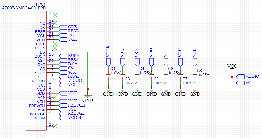 |
| Display connector and filter caps |
The circuit above is mostly self explanatory. I've created a connector component specifically for this display and here can be seen for example that the VCI and VDDIO are both connected to VCC. The VSS on the other hand is connected to ground in addition to BS (Bus Select) which sets the input as a 4-wire SPI bus. The four wires in question are chip select, data/command, serial data and serial clock. Additionally the microcontroller should control the reset and respond to the busy signal. More on that later.
Microcontroller
As already mentioned, the heart of the circuit is an ATmega328PB. The microcontroller circuit is quite simple. Display is directly connected to the microcontroller pins, as well as the clock crystal and the programming connector. The TMHU33 user input is connected with low pass filters like in the binary clock that I've shared previously. Additionally there is an activity led, reset button and some test points.
 |
| Microcontroller circuit |
One thing to note here is the PU (Pull Up) connection. Since the microcontroller is directly powered from the battery, we can measure the battery voltage from a microcontroller pin. This way the resistor connection (R1 and R2) is not constantly connected to the battery and can be switched off when not needed. There is of course a small voltage drop because of the internal FET of the microcontroller pin, but that effect is quite insignificant. The resistor values are also chosen to be as large as possible without being too big for the ADC input impedance (impedance should be 10k or less). The capacitor (C9) is there to smooth out any noise from the measurement. The clock crystal also has to be such that the circuit does not require additional capacitors (max 6pF according to spec).
The rest
The rest of the circuit is shown below in a schematic that is so compact that it's almost uncomfortable. I will share the full schematic later on in any case. There are a few things someone might notice here. First of all there is a signal called INT. That is a legacy thing that is not really needed here, however the serial line could technically be connected to the programming connector, since SPI0 block shares the same pins as the UART1 block on the used microcontroller. Using this serial line the data could be dumped from the device to the PC. For that reason there is a connection to the INT0 pin to wake up the microcontroller.
 |
| The rest of the schematic |
Another detail is the unconnected test point. This is the middle connection in case I want to power the device from two supercapacitors. This way I could solder the two capacitors in series directly to the PCB. Additionally there are two large capacitors (C21 and C22). These are for a bit of trialling how long the device could possibly operate from such capacitors in sleep mode. If the current consumption is small enough, it could be possible to change the batteries without losing the measurement data. This way the device could store really long graphs (a year?) without any interruptions.
Now the PCB is the fun part. I've spent really a lot of time making this design. Since I lack some imagination, I decided to make the PCB the same size as the Waveshare module as I've already mentioned. This includes the mounting holes in the corners and a notch on the bottom of the PCB for the flex cable of the display. The size of the PCB eventually caused some issues since there isn't really much space for all the components as can be seen in the pictures below. Another detail is that for some (historical) reasons I've decided to make the design vertical.. I actually didn't question it at all before writing this post, so I don't really have a better explanation.
 | |
|
As can hopefully be seen in the pictures, most of the components are located on the bottom side of the PCB, except for the programming connector and the activity LED. Additionally the reset button and the TMHU33 switch are on the edges of the board. Originally I wanted to use 2xAA battery configuration, but then I realised that there simply isn't enough space for that. I mean perhaps it could be done, but that is already a bit inhumane. I usually try to follow basic design rules regarding the layout and using 2xAA would require breaking a lot of those. Also there was already very little space for my name. :)
The circuit layout can easily be split into logical groups. The connector for the display is located at the bottom of the PCB and the boost circuit & filter caps are located in the near vicinity of the connector. I've decided to locate the battery holder on the right side of the PCB so that the the right edge will point downwards if the display is placed sideways, that way the joystick is on the right side and the battery holder can act as a stand. The joystick itself is located on the upper edge with all its circuitry. The power connectors and capacitors are also grouped into one place. The rest, which is mostly the microcontroller, clock crystal and the temperature & humidity sensor, are located on the left of the battery holder. The routing here is done manually and in my opinion it actually looks quite cool.
ps. Right here is the first issue in the design. I've broken my own rules and failed to add test points to the top side of the PCB. There isn't really much space on the top side, but there is a place for at least one test point on both sides of the flex cable. It might be difficult to see from the design, but it's easier to see from the photo of the final assembly.
Result
This post was mostly about hardware and in my opinion the result is very good in that regard. I wanted to add a diode and test points for a solar panel but eventually forgot to do that. Also there are no test points on the top side as mentioned above. Below are some pictures of the current state of the device. It's very much operational but the code was very quickly adopted from the previous revision, so it's quite ugly and unorganised. The time is still hard-coded, the measurement interval cannot be selected and there is no longer graph stored (because it will not fit into RAM memory).
 |
| Assembled unit number 2 |
There is also some errata that I've collected into the EasyEDA project. In addition to the issues above, the pads of the SW2 footprint are too small and the resistors around the temperature & humidity sensor are too close to said sensor. Also it seems that the connector for the display is a tiny bit offset, so the display cannot be exactly where it is marked on the PCB, because the short flex cable doesn't allow any adjustment on that axis (vertical in the picture above).
In the next part I will explain the basic code to drive this display, draw basic figures and print text. After that I shall explain how the temperature/humidity data is measured, stored and displayed. After that comes the fun part of adding input to actually set the time and the measurement interval as well as some other things (display modes?). Then there's of course the part of optimizing this code for maximum battery life and also measuring the actual battery life. So apparently this will not be a short project. I also hope I will not come up with too many improvement ideas along the way.. :)
Final words
I would say this project is progressing nicely so far. I've managed to design a PCB without any major problems or at least I haven't found them yet. The only issue has been my previous project that has taken more time than I would have hoped for. Also I have other projects that I want to start doing before this one is done. But I guess this fine. Also I have some other issues which might delay the next part of this topic.
After some coding I already regret the microcontroller choice. I might remake this later on with some better microcontroller, but I'm still determined to make this work using the chosen microcontroller. Though I've already got some "feature requests" that will make it tricky. Also originally I wanted to use the EEPROM memory, but now I kinda don't want to do that anymore. So everything will have to fit into RAM. That should be doable, since the EPD has built in memory for the picture data.
Another issue is the speed of the display update. I didn't check the datasheet well enough and apparently this smaller display is lacking some features that exist in the larger 4.2" display. I'm not sure if those features would really help with the speed and I will have to research that later on. The result is however that for example setting the time will be very slow on this device, but I'm quite sure I will come up with some solution to circumvent this issue.
ps. For some time I thought that EPD stands for Electronic Paper Display, but apparently it actually stands for Electrophoretic Display. Which kinda makes sense since that name actually represents the technology that makes the display possible and isn't any arbitrary name like "electronic paper".


