Showing posts with label ESP32. Show all posts

Thursday, May 6, 2021

ESP32-Radio (Part 2)

Introduction

As I've explained in part 1.5, I've had quite some issues in the beginning of the project. However I was able to design adapter boards for the display, buttons and the rotary encoder. They also required multiple revisions, but nevertheless they are now done and they are enough for me to proceed with the project. I've had a lot of issues while trying to make the buttons work well, but I think I've got the hang of it now. The display on the other hand is working nicely from the start and I will do further development in the final part. I've tried to make the adapter boards as generic as possible so that I can actually reuse them in some other projects or prototypes.

Display

Schematic

I've made a minimalistic adapter board for the RX12864H-BIW display from Raystar. I like this specific display since the it's quite cheap, compact and easy to use. This exact display uses the ST7567 driver and requires only two small external caps and basically nothing else. The downside is the FFC connector and a requirement for quite tricky mounting holes (also it's always out of stock at TME). I've also included smd solder blob type switches on the board for all the pull-ups and pull-downs that my project requires (hardwiring is bad) and finally a MOSFET for driving the backlight with a PWM signal. The schematic in all it's simplicity is shown below.

Adapter board for the RX12864H display from Raystar

The PSB, ERD and RWR connections are designed for the serial configuration that I'm going to use. These are specified in the datasheet. For the backlight resistors R2-R5 are connected in parallel, because a single 0603 resistor cannot handle such power that is going to be dissipated there (approx. 100 mA * 1.5 V = 150 mW). Typical power rating for an 0603 resistor is 1/16 which is 0.0625 W, so it's a good idea to split the current to at least three resistors. It would make much more sense to use a larger resistor but I only have a good selection of 0603 resistors. SW1 is also there for bypassing the backlight control in case it's not needed.

The only issue with this board is that the backlight will easily flicker if the input voltage varies even slightly. This happens especially in the device I am building since the current consumption of the ESP32 changes quite wildly. I've seen this issue in some previous project (while using ESP8266), but have forgotten it until now. Adding capacitors doesn't really help but adding a voltage regulator is an adequate filtering solution. The 3V3 is unfortunately not enough for the backlight since the forward voltage is 3.3-3.7V. For this reason I've decided to add an adjustable regulator and set it to 4V in the final design. The voltage drop of the regulator should be small enough for the device to work even with 4.5V input voltage (for very bad cables / power supplies). I was too lazy to make a new revision of the adapter with this regulator included, but perhaps some day I will. A good choice for an adjustable regulator is AP2127K-ADJ which is in a SOT23-5 case, can handle current up to 400 mA and has a small voltage drop. Additionally datasheet of the regulator has exact resistor values calculated for 4 V output. :)

The display is intended to be connected with the SPI interface. In addition to the standard SPI interface (Clock, Data In & Chip Select), the display uses typical D/C-signal (Data/Command, although it's marked A0 which probably means Address) and a reset signal. All this can be seen later from the final design.

PCB

I've made the PCB only slightly larger than the display. Only so that the mounting holes, connector and pin descriptions can fit on the board. This time I also remembered to include as much useful information as possible, for example the name of the driver chip, suggested resistor values, SDA/SCL mapping and C1/C2 voltage ratings (on the bottom, so not seen here). Also the FFC connector and smd solder blob type switches are on the bottom side. The top side of the PCB is shown below.

Adapter board for the RX12864H display from Raystar

The trickiest part was to do the mounting holes for the display module. There are four different details here. The largest hole (shown in grey) in the middle is for the flex cable. The flex happens to be so long that it can be folded under the display, through the hole and into the connector that is FPC1 in the middle of the board (on bottom side). Next there are two rectangles on both sides, these are for plastic clips that are used to attach the display to the PCB. Next are the two large through hole pads at the bottom of the display, these are actually for very narrow strips of double sided PCB that houses the backlight (6 LEDs and 6 series resistors). As a side note the max rated current for the backlight is 96 mA, which means 16 mA per LED, which is reasonably conservative. Lastly there are two small mounting holes in both bottom corners of the display, these are only 0.6 mm in diameter and 78 mm apart. Luckily my measurements were correct and JLCPCB was able to deliver the necessary accuracy that the display fits perfectly (at least two test units).

ps. The reason why a second revision of this board had to be made was that I simply didn't notice the small guide pins at the bottom of the display. Additionally I made the through hole pads too large and I honestly don't know why I did that mistake. I also forgot to add multiple resistors in parallel for the backlight, but that was not a big deal for a prototype.

Code

As already mentioned the display is connected with the SPI interface and pretty much imitates the HD44780 interface. There are a few things no note here however. First of all, this is a graphical display, so there is no hardcoded font data. Secondly the data is arranged vertically on the display unlike it is in many other displays. Lastly the datasheet (or any page on the whole internet) doesn't have any clear example on how to use this exact display. However after looking closely at the datasheet, I found all the necessary details and improvised the rest. I did take some pointers from this source, but I'm highly allergic to that level of code.

After configuring the SPI bus, the software should configure the display. The datasheet tells us that the bias should be 1/9. After that the boost level, regulation ratio and EV (?) should be set. Since the input voltage of the display is 3.3V and the typical voltage for the LCD panel is supposed to be 10V according to the datasheet, I've selected the boost level to be 4X, which would result in max voltage of 13.2V. I then selected the regulation ratio to be 6.0 so that the 10V is in the middle of EV setting (based purely on the graph in the datasheet). Lastly I've set the EV value to be 32 which is in the middle of the configuration range. After some trial and error, I've selected the perfect EV value to be 23, but that will vary from display to display. Additionally I've set the Y axis to be inverted, since the whole panel seems to be upside down and I didn't want to invert all the font data. The configuration process is shown below.

void rx12864h_configure() {
   rx12864h_cmd(RX12864H_BIAS_SEL | 0); // BS=0 -> 1/9
   rx12864h_cmd(RX12864H_START_LINE | 0); // Start line: 0
   rx12864h_cmd(RX12864H_SEG_DIR | 0); // MX=0 -> X normal
   rx12864h_cmd(RX12864H_COM_DIR | (1<<3)); // MY=1 -> Y inverted
   rx12864h_cmd(RX12864H_REG_RAT | 0b110); // Regulation Ratio
   rx12864h_cmd(RX12864H_SET_EV);
   rx12864h_cmd(0x17); // 0..63
   rx12864h_cmd(RX12864H_SET_BOOST);
   rx12864h_cmd(0b00); // 00=4X, 01=5X, 10=6X
   rx12864h_cmd(RX12864H_PWR_CTRL | 0b111); // VB=1 VR=1 VF=1
   rx12864h_cmd(RX12864H_DISPLAY_ON | 1); // Display on
}

After the configuration of the display the picture data can simply be sent to the display one 8-bit column at a time. Unfortunately the counters don't wrap, so they have to be incremented/reset manually. The whole update method is represented below. Since the display is 128 x 64 pixels and has a vertical configuration, there are exactly 128 columns and 8 "pages". The data is sent in bursts of 128 bytes, so one "page" at a time (as a single transmission event).

void rx12864h_update_display(char *picture) {
   for(uint8_t i = 0; i < 8; i++) {
      rx12864h_cmd(RX12864H_PAGE_ADDR | i);
      rx12864h_cmd(RX12864H_COL_ADDR);
      rx12864h_cmd(0x00);
 // Clear column counter

      rx12864h_data_burst(picture, 128);
      picture += 128;
   }
}

Lastly there is the backlight. "Fortunately" configuration of PWM is "very simple" in ESP32. I use lot's of quotes, because I can see how it's made "more simple" for the end user and somehow it's still more complicated than in an AVR. Anyhow, I've configured one pin to output an 8-bit PWM signal with the frequency of 1 kHz and that seems to work just fine to control the backlight. I will not share an example here, because it can easily be replicated from here (also it's just ugly boiler plate code).

Buttons

Schematic

I've made a minimalistic adapter for two buttons and one rotary encoder. Except it's not so minimalistic since the board accepts two different types of buttons and two different types of rotary encoders. The buttons are completely different (D6R90 from C&K and B3FS-4002 from OMRON), but the rotary encoders (specifically EC11J15 and EC11E15 from ALPS) are basically the same except for the mounting (surface mount and through hole). I've wanted to include these two specific button types since they both are very good in quality but differ quite much in the height. If I were ever to design a case for this device, the D6R90 would look quite nice poking from the enclosure by itself (as I've done previously in some other project, albeit with cheaper buttons).

Additionally there are pull-ups and debounce filters on the board. Unfortunately the pull-ups are done incorrectly on this board, since the pull-up resistor is on the wrong side of the series resistor. This means that the resistors work as a voltage divider when the button is pressed, which is okay if the values are chosen correctly. However this means that the rise time of the button signal is significantly longer than the fall time. Additionally the rotary encoder has a minimum working current of 1 mA (as stated in the datasheet), which limits the pull-up resistors to 3.3 k when the used voltage is 3.3 V. Apparently the using the rotary encoder with a smaller current will introduce much more noise as was stated in some source, which I unfortunately no longer have, sorry. The schematic is shown below.

Adaptor boards for D6/B3FS series buttons and EC11 series rotary encoder

As can be seen in the schematic, the two button types and rotary encoders are connected in parallel, since only one of these can be soldered at a time.

PCB

The PCB is equally simple in this case, the different buttons and the different rotary encoders are located on top of each other so that only one type can be soldered at a time. This was quite simple and logical thing to do in my opinion. The board is shown below in all its glory. I didn't even bother adding a ground plane and I probably should, since the boards look very odd without a ground plane.

Adaptor boards for D6/B3FS series buttons and EC11 series rotary encoder

The only issue with this current board itself is that I forgot to relocate the SW5 and SW7 labels. :(

ps. The reason why the second revision of this board had to be made was that I used ready made components in the first revision and the symbol for the B3FS had wrong pinout, which means that the button was constantly shorted. Also the EC11J15 did not fit in it's footrpint. You might ask how an SMD component cannot fit into its footprint that was supposedly made by the manufacturer and I simply do not have an answer for that. I only know that it physically did not fit, since the tap at the bottom of the component did not fit into the hole in the board. Moral of the story, never use ready made components. If you want something done, do it yourself.

Software

The buttons are very simple devices. I mean they should be. However I've spent quite some time trying to make them work properly with the ESP32. I suppose the source of these issues is that I tried to use GPIO interrupts to read the buttons as I've done with many AVR projects previously. It seems that compared to an AVR, the ESP32 is much too sensitive for detecting the falling edge. I suppose I could have used detection of the rising edge but then the schematic would need to be changed and that's just stupid. I've spent many hours trying to make this work using interrupts, but then it took only a few minutes to make it work after I gave up on the interrupts.

Reading the properly debounced buttons without an interrupt is very simple, especially when using FreeRTOS. You basically make an endless loop with a delay statement, that checks the state of the button pins and compares to the previous state. This way a falling edge can be detected, which means that the button has been pressed. Fancier features like the long press support can be added later of course, but edge detection is the basic principle for reading a button press.

The rotary encoder is a bit more difficult. There are two pins in this encoder and they are shorted in specific order when the encoder is turned. The specific order is gray code (not binary) for good reasons. However we don't really need to care about that, we just define the four states that can be created with two pins, and try to detect specific state changes. The principle is basically the same as with the buttons, but here we check the state of multiple pins instead of just one. The state change is then interpreted as one clockwise or counterclockwise step. Below is a picture that shows the four stages of a rotary encoder (taken from the ALPS datasheet).

Gray code of a rotary encoder

Let's assume that the left dotted line is at state 0 and the right one is at state 2. In this case we can, for example, detect state changes from 0 to 1 and from 2 to 3 as one clockwise step. Similarly a change from 3 to 2 and from 1 to 0 would mean one counterclockwise step. And that's basically it. Below are first some example definitions for pins and rotary encoder states. The states are defined similarly to the picture starting from the left dotted line.

#define KNOB_RE_A_PIN 27
#define KNOB_RE_B_PIN 26
#define KNOB_BUTTON_PIN 14

#define RE_MASK ((1ULL<<KNOB_RE_A_PIN)|(1ULL<<KNOB_RE_B_PIN))

#define RE_STATE_0 ((1ULL<<KNOB_RE_A_PIN)|(1ULL<<KNOB_RE_B_PIN))
#define RE_STATE_1 ((1ULL<<KNOB_RE_B_PIN))
#define RE_STATE_2 (0)
#define RE_STATE_3 ((1ULL<<KNOB_RE_A_PIN))

After that we can make a task for reading both the buttons and the rotary encoder. I've also specified defines for each action, since they cannot really match with the pins (at least in case of the rotary encoder). Another remark is that I've used the GPIO_REG_READ macro instead of the usual gpio_get_level simply because there's no need to use the latter one. I suppose the latter one would also have some unnecessary overhead. Lastly the actions are sent to another task with the help of task notifications, which is a great feature by the way. In any case here's the example code.

static void read_buttons_task(void* arg) {
   uint32_t prev_buttons = 0xffff;

   for(;;) {
      vTaskDelay(10 / portTICK_PERIOD_MS); // 10 ms delay
      uint32_t buttons = GPIO_REG_READ(GPIO_IN_REG);

      if ((prev_buttons & RE_MASK) == RE_STATE_0 && 
            (buttons & RE_MASK) == RE_STATE_1)
         xTaskNotify(gpio_task_h, KNOB_CW_BIT, eSetBits);
      if ((prev_buttons & RE_MASK) == RE_STATE_2 && 
            (buttons & RE_MASK) == RE_STATE_3)
         xTaskNotify(gpio_task_h, KNOB_CW_BIT, eSetBits);

      if ((prev_buttons & RE_MASK) == RE_STATE_1 && 
            (buttons & RE_MASK) == RE_STATE_0)
         xTaskNotify(gpio_task_h, KNOB_CCW_BIT, eSetBits);
      if ((prev_buttons & RE_MASK) == RE_STATE_3 && 
            (buttons & RE_MASK) == RE_STATE_2)
         xTaskNotify(gpio_task_h, KNOB_CCW_BIT, eSetBits);

      if (prev_buttons & (1ULL<<KNOB_BUTTON_PIN) && 
            ~buttons & (1ULL<<KNOB_BUTTON_PIN))
         xTaskNotify(gpio_task_h, KNOB_BUTTON_BIT, eSetBits);

   prev_buttons = buttons;
}

SPI Issues

As I've already understood from the start, this project would require something to be able to use multiple SPI devices on the same bus. However I wasn't sure how big of a deal it would be. Originally I might have thought that the SPI library has some thread safety built in, but apparently it doesn't. It actually took me quite a while to understand why the device was crashing when I tried to change the volume. Since the VS1053b chip has a separate control bus, the volume control was clashing with the upload of audio data and thus the device crashed (with a ~50% probability). So I technically had to solve this issue before I even connected the display.

As the warning in the link above states, there are two options for using multiple devices on the same bus. One would be to refactor everything nicely into one task. I didn't want to take this path, since I would like to have the display and audio decoder as separate as possible. The second option is to just use a mutex. This was a much nicer option, even if it might not be as efficient (see background here). (I might actually rethink this later on, especially if I want a high and consistent refresh rate for the display. After all, the common task can be in the main module and only call respective functions from the display & audio decoder modules.)

With this info the solution is simple, just create a mutex object in the main module and pass it to both the display and the audio decoder modules. There is still a possibility that for example the volume change will interrupt the update of the display, but it will take a tiny amount of time and it will not crash the device. Previously I wouldn't have known how to measure or debug these kind of things, but luckily I now have a logic analyzer and was able to capture these events. For your viewing pleasure, below is a screenshot from PulseView with decoders added for audio decoder data and display control & data.

SPI traffic of the audio decoder and the display captured with PulseView

The SPI frequency is set to 1 MHz in this test, because I have a rather cheap 24 MHz logic analyzer and it's not really usable beyond 2 MHz. Also with 1 MHz it was very easy to capture such a case as seen above. The audio data is sent in bursts of 32 bytes as already explained. For this reason the display update can interrupt audio upload, since there is no priority whatsoever. The display data on the other hand is sent one "page" at a time, which is 128 bytes. Additionally the control data for the LCD (as explained in the software part) can be seen in the picture, since the control and data are sent to one SPI device as seen by the ESP32 (unlike for VS1053b).

Let's do some math here just to measure what kind of performance can be expected from the device. Let's assume that the SPI frequency is 1 MHz and we have an 128 kbps audio stream. A single display update would require 128 * 64 bits of data to be transferred (without any overhead included). We also know the overhead for the control, which is 3 bytes per page so 3*8 bytes in total. With this info we can calculate the (theoretical) maximum refresh rate of the display. 

(1 000 000 - 128 * 1024) / (128 * 64 + 3 * 8 * 8) = ~100 Hz

This is some very good performance. Even with 320 kbps stream, the refresh rate would still be ~80 Hz with 1 MHz SPI frequency. We should however consider the unilization of SPI bus, since the ESP32 has also other tasks (even if DMA is used). If we consider 30 Hz refresh rate, the utilization would be (128 * 1024 + 128 * 64 + 3 * 8 * 8) / 1 000 000 = ~14 %. That doesn't really seem much, but we're not taking overhead into account (apart from LCD control). Nor are we taking into account the overhead that comes from the 32 byte bursts for the VS1053b chip. Below is a zoomed out picture of ~1 second timeframe with a 320 kbps stream playing and 3 Hz display refresh rate.
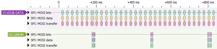
Zoomed out SPI traffic with 320 kbps stream and 3 Hz display refresh rate

From the picture it kind of looks that the utilization of the SPI bus is around 50% and it looks like it would be ~100% with the 30 Hz display refresh rate. This is however not a very good analysis since it might look bad simply because of the fancy graphics. Regardless of that we have the option of increasing SPI frequency to significantly reduce bus utilization. The maximum frequency for LCD is 10 MHz and for the audio decoder also 10 MHz, although there is a catch regarding the configuration that I will explain later. With 10x speed increase the device shouldn't have any issues at all. This math is necessary especially if we want to add a spectrum analyzer to the device. And we definitely want to do that later. :)

Result

With the hardware and software shown here, I was able to control the radio and make it display useful information. The first thing to do was obviously volume control and after that followed the menu to control all settings of the VS1053b chip and also change the radio station. The display looks very cool with its blue backlight but it was also quite useful while displaying the buffer usage and the signal strength in real time. The only issue is that the edges of the display look annoyingly bright without any case, as compared to a standard eBay 128x64 LCD with a metal bezel. At least I can say that the picture quality is significantly better.

Also here are the links for display adapter and button adapter EasyEDA projects. It seems that EasyEDA is using some new OSHW Lab platform for sharing projects and I have to say that it looks unfinished. However the EasyEDA project sharing was not that much better so who cares.

Final words

Apart from a few slowdowns, this project is quite on track. I might even be able to finish it before my personal deadline, which is in September.

It's worth noting that while the SMD version of the rotary encoder is quite nice, it's also 2+ times more expensive than the through hole variant at least at LCSC. I wonder why it's like that.

Sunday, May 2, 2021

ESP32-Radio (Part 1.5)

Introduction

It's been quite a long time since my last post and that is because I felt unreasonably tired lately, which might have been related to my work. In any case I've had a lot of progress with this project even if I was stuck with very basic, vary fundamental and very annoying issues for some time. Most of these issues are related to the basic things discussed in part one, so I'm writing this part "one and a half" before part two. I've also learned quite a few things related to the FreeRTOS that is included in the ESP-IDF. So let's discuss these few little things.

Buffer overflow

As discussed in part 1, the radio server seems to send data at a much faster rate than it's supposed to right after the connection has been established. I suspect this is done so that the client can fill the audio buffer quickly and start playing the audio. Without any check the audio buffer in ESP32 would fill up quickly and overflow while also making annoying noises. I fixed this issue by making the code loop until there is some free space in the buffer. This works "nicely" since the ESP32 has two cores and the other core can run the task that is responsible for sending the audio data to the decoder chip (among others).

At this point I think that is the worst way to solve this issue. The problem is that the code is simply stuck without the possibility to run any other code on that core. The correct way would be to use FreeRTOS Stream Buffers which would allow task switching in case the buffer is full. Using this would however require quite a lot of rewriting, which I didn't (yet) want to do. Eventually I realized that simply using vTaskDelay (in the loop) with a minimum time, would basically do the same thing. The code would check whether the buffer is full and issue this wait statement if it is. This in turn would allow other tasks to run on this same core instead of just running NOPs. Before this change the device definitely had some hiccups from time to time, but this change significantly improved performance and the issues are now gone.

VS1053b MIDI

As discussed in the first part, the VS1053b board from eBay has a design flaw, where the IOs are not pulled down as they are supposed to (as shown in the datasheet). This is related to the fact that this board is possibly the shittiest design that I have ever acquired from eBay. As explained here, "most modules will start in MIDI mode". There is also a link that points here. I originally failed to understand the fact that after making these "few register writes", it is necessary to make a soft reset so that the chip can read the state of the pins at boot.

Interestingly the device worked quite fine with my faulty code for a long while but then it simply stopped working. The funny part here is that when the device boots into MIDI mode, the AUDATA is configured to 44101 (which is okay for most servers and means 44100 Hz sampling rate and stereo mode) and the DREQ pin is high, which means that the device is constantly draining data and not playing anything.. However the latter link has a picture of pins that have to be physically connected (circled in green in the picture below) for the device to boot properly without any software fixes. I should have used the physical fix right from the start, but instead I wasted a lot of time making workarounds to detect the "stuck device" and rebooting it. That was a huge waste of time, cannot recommend. However here is the link to the original explanation right from the manufacturers of the chip.

VS1053b Board Buzzing

As I've explained in the first part, the board that I have, was making a very annoying and rather loud buzzing sound. The sound was coming from the board itself and couldn't be heard in the audio output. I spent quite some time poking around the VS1053b board without any luck. I also tried measuring voltages on the board, again without any luck. I tried to live with but after some time I was too annoyed again. It almost gave me headaches since it was so loud. Then I remembered how these things should be debugged: simply by taking a cap and poking it in different places. After some poking the buzzing suddenly stopped. After two months of ~constant buzzing it simply stopped (I had it connected to a USB port and thus it was on all the time my PC was on, just to see that it doesn't crash or disconnect).

And here's the explanation. The main output cap (C1) of the 1V8 regulator (U3, the core voltage) was located quite far away from the regulator. The regulator in question is AMS1117 and according to some datasheet it requires an insane 22 microfarad output capacitor. This capacitor should obviously be as close to the regulator as possible. Instead it's a few centimetres away and the connecting tracks are routed god knows where (shown in red and purple in the picture below). There is however a 100 nanofarad capacitor (C18) right next to the regulator, which, I suspect, was simply faulty in some way. After I've desoldered both 100n capacitors (3V3 and 1V8) and replaced them with 4.7 microfarad capacitors (C18 and C17 in the picture), the board has not made any sound (except for the audio output of course).


VS1053b evaluation board from eBay

I tried to understand this later on with the help of an oscilloscope without any luck. My final conclusion is that the original capacitor C18 in the picture above was faulty, since the board made no audible sound even without anything soldered in its place.

I've also acquired a second board to have just in case, and that board was even worse. It had the VS1003 chip instead of VS1053 and had a 2.5 V regulator instead of 1.8 V one. This part needs clarification. For the VS1053b the voltage ranges are 2.5 .. 3.6 V for AVDD, 1.7 .. 1.85 V for CVDD and 1.8 .. 3.6 V for IOVDD. So two regulators (3.3 V and 1.8 V) are enough for the VS1053b. For VS1003 however, the respective voltages are 2.6 .. 2.85 V for AVDD, 2.4 .. 2.85 for CVDD and CVDD-0.6 .. 3.6 V for IOVDD. Since the board looks the same as in the picture above, I assume that on this board AVDD is connected to 3.3 V. And the question is why would you do that? Absolute maximum ratings exist for a reason. Picture of the board is shown below.


VS1003 evaluation board from eBay

Perhaps less surprisingly this board didn't work correctly. It usually started okay and then the audio just faded out after some time of playing. I tried to debug it for a while and then simply gave up because the board is clearly not worth it.

Header issues

As I've explained in the first part, the server will send an HTTP header after the connection has been made. The new thing is that this header might vary a bit between different servers. This might be an issue, because I've only tried this with exactly two different servers and found three different issues. Here are the issues that I've encountered until now.

One server doesn't seem to send the sample rate of the audio at all. This is not an issue, since the sample rate can be read from the decoder chip and more specifically the AUDATA register. The value should be adjusted simply by (AUDATA >> 1) * 2 to get the actual value (to lose the stereo bit).

One server sends some garbage instead of the stream name. This is very annoying. However it can be easily solved by not using this value. The name of the radio station can simply be hard-coded with the URL address of the server in the device. I had an idea of fetching some channel list automagically for example from SHOUTcast API, but that's for another time.

One of the servers seems to use "content-type" as the tag while another uses "Content-Type". Solution for this is simply to use tolower function before trying to detect the tag.

Prototyping issues

This prototyping phase has lasted quite long for this project and the reason is that I want to try as much of the final implementation with it as possible. By as much as possible I mean the display and the buttons & rotary encoder. Since the pins of the ESP32 can be assigned quite freely, I can change the schematic based on the board design, to make the routing as simple as possible. The prototype can then be easily reconfigured to test the new connections before ordering the PCBs.

However there are a few issues related to the prototype. The worst issue is that because of the long wires, the device will easily pick up noise. I suppose it's not very dangerous, but suddenly hearing the audio at the maximum volume is certainly not fun. I've noticed this already at my desk and then I definitely noticed this when testing at the location where the end device is supposed to be used. Basically switching a noisy lamp or a power supply on or off will make the device output audio at full volume and also somehow garbled. Luckily the volume goes to the exact maximum, so it's very easy to detect as an error case.

I've concluded that this is not very good even for a prototype. So with my newly knowledge of FreeRTOS, I quickly made task that regularly checks whether the volume is at maximum and lowers it to some sensible level if it is. In retrospect, this fix had one of the best effect / effort ratios of all the things that I've made for this project.. Unfortunately the audio is still garbled so this fix doesn't solve that. I suppose it would require restarting the audio decoder. That would then require logic for finding the beginning of the next audio packet in the stream, or it would simply glitch for a while until the decoder gets the next header and recovers. In any case this should not be an issue with the final design and until then at least I don't need to hurt my ears.

Another issue related to the prototype is that some wires usually end up being near/above the WiFi antenna of the ESP32. This seems to be an issue because it introduces some noticeable noise in the audio output of the device. This is rather annoying because I can clearly hear it whenever there is a silent moment in the music. Interestingly there are no audio cables near the WiFi antenna, which means that the voltage regulation of the audio board is not very good. However it's enough to just insert some item between the antenna and the wires to get rid of this problem. For example a USB memory stick is very much enough. The signal strength will obviously be worse after this, but at least there is no noise in the audio whatsoever. This "fix" is okay for the prototype and should not be an issue with the final design. This is one good reason to follow the esp32 hardware design guidelines. :)

Final Words

I can only say that a lot of lessons were learned here. A simple RTFM can be applied here of course but it seems that FreeRTOS contains quite a few new things for me to learn. Also the issue with MIDI was just a very annoying mistake. The rest are simply adopting to the environment.

Sunday, January 17, 2021

ESP32-Radio (Part 1)

Introduction

Aim of this project is to make a physical, WiFi connected, Internet radio client (regardless of the slightly confusing name). Unlike many other projects, this is not my lifelong dream or anything, it's just that I'm very intrigued by connecting ESP32 to an audio decoder chip (VS1053b in this case) and by various possibilities these bring to the mix. I thought of this originally already when I was using an ESP8266 before ESP32 was released but I did not have enough knowledge back then and failed to google such project, so cannot really say if someone has already done such a thing then. Later on I had this idea again already with an ESP32 and after a quick search I found this mess. After skipping through the video without having the patience to watch it completely, I just decided to make one, although without the wire spaghetti and the Arduino crap.

Unlike other projects I've described here, I have a need to make this work as soon as possible. So this project could develop very fast (and have obvious issues) or it might never be finished. Who knows? However there's much to discover and learn here. I will start prototyping this project with eBay modules, so in the beginning it will be a mess of wires (like in the video) and will mostly be about the code, which I am making mostly from scratch, since I simply don't want to read 5k+ lines of code. There are also many new things here for me, both in software and in hardware, so this might get interesting.

I had some difficulties finding sources for this project (that don't involve Arduino) but here's one application note from microchip, here's one post in stackoverflow and one assignment(?). Also here is an Arduino library for VS1053b. Other sources are mentioned later on in this post. These were however a bit difficult to properly use in the text.

Background

Technically this project is very simple. An ESP32 is used to open a connection to a specific server which then sends audio data back to the ESP. The ESP should buffer this data to even out network latencies and stream it to the VS1053b decoder chip. The decoder chip then directly outputs analog signal which only needs to be filtered and possibly decoupled. The decoder chip is also able to output audio in a digital format, which would make it possible to connect it to a proper DAC if necessary.

SHOUTcast

The basic idea of SHOUTcast (or icecast) is basically to stream audio data. There's not much into it. First the server will transmit some kind of a header, which includes station name, genre, bit-rate and such. After that the server will start outputting audio data frame by frame. I'm not sure about the other formats, but at least MP3's contain a header in each frame, so the decoder chip can get all the needed information from the first few bytes of each frame. The server is also capable of sending metadata between chunks of audio data if the client requests so. The resulting data-stream would look as shown below assuming the metadata is requested. If the metadata is not requested, the stream only contains the header and continuous audio data.

[header] + [audio data] + [meta size] + [meta] + [audio data] + ...

1. The end of the header can be easily detected from the standard "\r\n\r\n" ending.

2. The size of the audio data chunk is specified in the header with the "meta-int" tag.

3. The "meta size" x 16 tells us how many chars there are in the metadata. Metadata is padded with zeros, if the length is not divisible by 16.

VS1053b

This is a very powerful chip that is able to decode MP3, AAC and OGG formats among others. The chip is also able to directly output analog signal as already mentioned and can drive headphones directly. The downside to this chip is its price, pitch of the pins and the amount of filter caps and routing it requires. However the good part is that it doesn't really need to be configured in any way. Basically it's enough to set the internal frequency, output volume and then just stream any supported audio data through the SPI bus. This makes the project very very simple. However there's much more to this chip, but that's for another time (but definitely for this same project).

Electronics

I will not provide any schematics here, since I simply improvised some connection between the ESP32 and the VS1053b. There is one SPI bus with two CS (Chip Select) pins, one for data and one for control. Additionally there is a reset signal and DREQ (Data REQuest). All this is exceptionally well documented in the datasheet. I used an ESP32-T development board, some VS1053b module from eBay (the oldest design I suppose, the one that doesn't look like an Arduino shield) and obviously DuPont cables.

A quick note here about the decoder module from eBay. It seems that the proper filter caps for the chip power are missing. Possibly for this reason the existing caps are making high pitched noise, which is quite loud and very very annoying. There is no noise in the audio output however. Additionally according to the datasheet the GPIOs of the chip should be connected to ground if not used, and they don't seem to be connected to ground in this board. This might be the reason that the chip does not automatically decode incoming MP3 audio and requires a few specific writes to do so.

I've also decided to build a prototype of the whole device using similar modules. However there is no such module for the display I want to use, so I had to design one myself. While at it, I also made a module that would fit a rotary encoder of my choosing and two buttons with pull-ups and filters. But that is for the next part.

Code

I've programmed this device using a lot of trial and error. The result can be split into five easy steps. This could be explained with many more steps, but I would like to strip down some things, like the ever changing API of ESP32. I only want to explain the general idea here.

Step 1, HTTP(S) GET

The first step after opening a connection to the server, is to make a HTTP GET request. It's a pretty standard request with the only exception of "Icy-MetaData:1" which tells the server to send the metadata amongst the audio data. The metadata is sent only if it has changed since the last time, so that it doesn't waste bandwidth. If the metadata has not changed since the last time, the server will still transmit the "meta size" byte, but it will be zero. Additionally there is an "Accept: */*" string which will tell the server that we accept any data. I suppose with this we could filter out formats that we don't support. Below is an example of the HTTP request, the WEB_PATH, WEB_SERVER and WEB_PORT have to be specified separately like in the http_request example. I have only tried the servers that use HTTP for now, but the same should work for ones that use HTTPS, just with different function calls.

static const char *REQUEST = "GET " WEB_PATH " HTTP/1.0\r\n"
    "Host: "WEB_SERVER":"WEB_PORT"\r\n"
    "User-Agent: esp-idf/1.0 esp32\r\n"
    "Accept: */*\r\n"
    "Icy-MetaData:1\r\n"
    "Connection: close\r\n"
    "\r\n";


Step 2, Parse header

The HTTP header can be used in this case to read the name of the stream (icy-name tag), genre (icy-genre tag), bit-rate (icy-br tag), audio format (Content-Type tag) and such. The bit-rate, sample-rate and audio format can be also read from the audio stream or the VS1053b chip after it starts decoding so it's not necessary to read these from the header. However it is necessary to read the icy-metaint value if the metadata has been requested. Other tags do not really affect functionality but are still good to fetch for example for displaying info on an LCD (like in the following parts of this project). Note: the Content-Type tag will say audio/mpeg for MP3 and audio/aacp for AAC.

Parsing the header is quite simple. The re-entrant strtok_r function can be used to first split the received data into lines and then another call can be used to split the tags and the payload. For testing these kind of things I like to use the C Playground. I just dump some example data from the device and try to parse it in the C Playground. It really speeds up the development process when I only need to test one piece of code and don't need to recompile the whole project and reprogram the ESP32. At least I'm not good enough to be able to write such code from the first try.

Speaking of testing, all the data can also be easily fetched on a PC using Unix tools. This could be done for example using wget as described here. I've personally also used curl. Both of these commands have to be terminated manually or they will keep loading data indefinitely. There is also a nice Unix tool called xxd that can be used to view hex data. Combined with less, xxd should be enough to inspect the stream data. Both of the commands also request the meta-data so that all that is written in this post can be easily verified.

wget --header="Icy-MetaData:1" -S -O reply.txt [url]
curl -H "Icy-MetaData:1" -i [url] --output reply.txt
xxd reply.txt | less


(Step 3, Parse metadata)

Technically audio data comes after the header, but in my opinion this step fits here better. Reading the metadata requires first waiting for "metaint" amount of bytes of audio data. After that, one byte should be read from the stream and multiplied by 16. The result is the amount of bytes that should be read as metadata (and not transferred to the decoder chip). After reading these bytes, the software should continue buffering audio data. An example of metadata is shown below.

StreamTitle='title of the song';

Parsing this syntax is quite annoying since the ' character can appear in the middle of the string. However I'm not sure if the ; character can appear in the payload. If it's not allowed, the whole string could be first split by the ; character and then = character, after which the first and the last character could be discarded.

Another issue here, at least at this level of programming, is UTF-8. Since we are making a simple embedded system, we do not want to support 1 112 064 different characters that the strings may contain. For this reason there should be at least some check that would simply replace the characters that our device cannot display with an underscore or any other character. I suppose for European radio stations it's enough to support Latin characters and the same but with all kind of hats (like åäöáàâ etc).

Step 4, Buffer audio data

Since there might be rather long latencies in the WiFi/Internet connection, some audio data should be buffered before forwarding it to the decoder chip. A simple circular buffer should suffice in this case. This source states that 300ms buffer should be enough, however I made a much longer buffer since there is plenty of memory in the ESP32.

Making a circular buffer is easy, it's just a large enough array with a pointer that wraps around to the beginning of the array after reaching the end. There should actually be two pointers, one for writing and one for reading. Special care should be taken so that the pointers don't pass each other, which would cause an ugly glitch in the resulting audio. It took me some time to implement this because of the way these two pointers are incremented.

The write pointer is incremented with whatever amount of bytes the receive function manages to receive from the Internet. That cannot really be specified, although I could make some function to write only until 32 byte boundary in the buffer. The read pointer is however always incremented by 32, because the datasheet specifies that at least 32 bytes can be written when DREQ goes high. For this reason I've implemented it in such a way that it does transmit exactly 32 bytes. Now this poses an issue, because we cannot check whether the read pointer is equal to write pointer, because there's 31/32 chance that the read pointer will skip write pointer and we will have a glitch. For this reason I've decided to make a check like so: read_ptr / 32 == write_ptr / 32. If the previous statement is true, the buffer is "empty" and that is technically an error (since the internal buffer of the decoder chip is quite small) and no audio data should be sent to the decoder (since there is no new data).

Originally I've expected the buffer never to overflow, since technically the decoder should consume the data at the same rate that the server sends it. More over I've assumed that the client (my device) should buffer some data first before sending it forward to the decoder. However that is apparently not quite so. It seems that the server sends data much faster right after opening the connection. I suppose this is so that the client can both fill the buffer and start playing immediately. This caused buffer overflows in my device, so I had to throttle the reception, because there's simply not enough memory for the amount of data some servers send. Making this functionality was easy, since the incoming data is processed byte by byte. The code was reduced to a simple "while((read_ptr + 1) % AUDIO_BUFFER_SIZE == write_ptr);" since reading is implemented in an interrupt and will not be prevented by this loop. This check should however be done before incrementing the pointer so that the device will not think that the buffer is empty.

Step 5, Transfer audio data to the decoder chip

As already mentioned, the easiest implementation is to transmit 32 bytes whenever the DREQ signal of the VS1053b goes high. However there might be large delays when receiving data from the Internet and the internal buffer of the decoder chip might not be enough for such a time. For this reason I've used a timer that calls an interrupt handler. This interrupt handler will then transmit audio data to the chip whenever the DREQ is high. This will interrupt any other ongoing tasks like the data processing, however it will not interrupt anything critical since those tasks should run on the other core and cannot be interrupted by the user program (AFAIK).

Making the transfer itself is quite simple. First the code should check whether DREQ is high. Then it should check whether there is at least 32 bytes of data in the buffer. If both checks pass, 32 bytes should be transmitted, the read pointer should be incremented by 32 and wrapped around if necessary.

Result

The result of this post is a completely hard-coded ESP32 Web Radio player that works mostly. It successfully connects to unsecured HTTP servers and streams data. It can also successfully strip and decode the header and metadata and print the results via serial line. The next step is to add a display, some inputs and make it configurable.

It feels amazing that less than 500 lines of code (excluding the WiFi and Internet connection code) is enough to make a hard coded Internet radio player. And most of this code is mostly written from scratch by me. However the length of the code might grow drastically as soon as the display is added and "hardcodeness" is removed. :)

Final words

This project is progressing quite rapidly. However I will need a breakout board to be able to prototype with the display that I want to use. And speaking of which, I only have one such display and more will be in stock in ... April apparently. I am not joking. This project might thus take quite a long time to be fully functional. I just hope I can have the first prototype PCB before my next vacation. :)

The most unfortunate thing about this project is that I've started it using the oldest ESP32 module that I had and there has been at least two new chip revisions after that. I don't really know if this affects anything in a meaningful way though. Additionally I also hope that this device will work in the location that it is designed for since I cannot often test it there. It might require an external WiFi antenna, but fortunately ESP32 modules with an external antenna are available.

Spoiler: I've been researching the VS1053b chip and there seems to be all kind of features including bass/treble control and plugin support that allows both an equalizer and a spectrum analyzer. With this it would be easy to make some kind of audio visualisation on a display or using external LEDs. In short, this decoder chip is very capable and I'm very interested in researching some of the available features.

Thursday, August 27, 2020

Tiny ESP32 board

Introduction

This project actually made me realise that the most important thing isn't what you're doing but it's why you're doing it. I've previously used a very simple ESP32 adaptor board from eBay, the one that only has the place for an ESP32, two buttons, two pull-up resistors, two pin-headers and a text "161015" on it. The reason I used exactly this board is that it doesn't have an integrated regulator circuitry which made it possible for me to accurately measure the current consumption of the ESP32 itself (including a very low current consumption of "deep sleep") without the effect of the voltage regulator. This board however isn't very good and at some point it wasn't very cheap either. For example the board lacks probably the most important thing a board can have, which is the required capacitor (the datasheet recommends 10uF) for the ESP32 module. Since this is a development board, the power is often connected with some random wires. In some cases the resistance of the wires is just too large and the ESP32 starts crashing because of low voltage situations. Additionally the board is large enough to have an usb connector and an optional regulator. Another important thing is the programming connector, which is also related to the previous post.

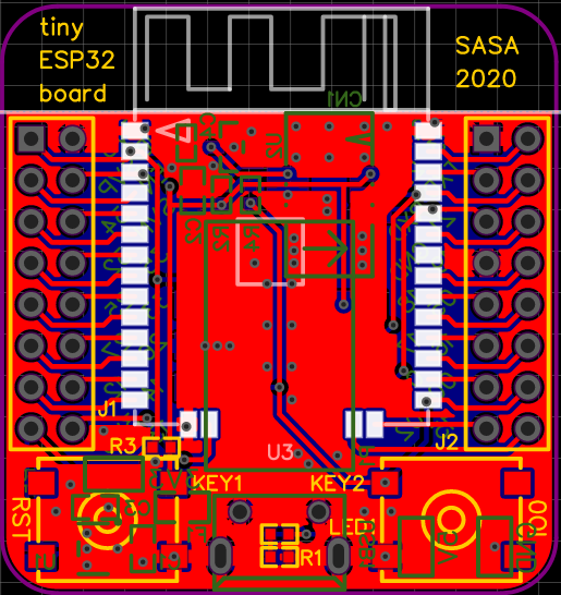
This is the reason why I decided to make my own adaptor board with blackjack and hookers.. I mean with an optional voltage regulator, USB connector and not one, but two programming connectors. I've also decided to add a stand-by LED, voltage monitoring chip and test-points for the power connections. Obviously all of the components are optional on this board except the ESP32 and the pin-headers. Additionally the original board had all the ESP32 pins connected to pin-headers. I've decided on the other hand to connect only those that can be easily used with the internal flash chip. For some reason I've also decided to make the PCB the same size as the eBay adaptor. I thought that it would be big enough for all the features and eventually it was.

The reason for the first sentence in this intro is that I originally thought I can just add all the features to this board, including the programmer part. Then I realised that I would just recreate the DEVKIT or similar development board. I also quickly realised that the board is simply too small to include all the parts and the programming connector which I really wanted to include. Eventually I realised that it really makes no sense to add everything to the board, since the main thing I want is a minimal development board that would have the programming connector and that I could use to measure the current consumption of the ESP32. For other purposes I could simply use ready made development boards. The USB connector and the integrated regulator is however such a nice feature that I've decided to keep that and simply add a "SMD solder blob" kind of switch. This way it's possible to completely separate the regulator from the ESP32 for accurate measurements. This approach is not as easy to use as a switch, but on the other hand it doesn't need to be "switched" often, it's very compact and has low resistance.

Schematic

The schematic is fairly simple, the main parts are the ESP32 and the pin-headers. Also there are the same two buttons and pull-up resistors, although there is an optional voltage monitoring chip instead of one of the resistors. Then there is the already mentioned USB connector and the voltage regulator. Lastly there are two programming connectors (50mil and 100mil), some test points and the stand-by LED. In reality the connectors could not fit properly on the board, so they are placed so that only one of them can be soldered at a time.

PCB

The board was made to very much mimic the original eBay board. The ESP32 module is on top, two pin-headers on sides and two buttons on the bottom of the board. The stand-by led is between the buttons. The bottom side has the voltage monitoring chip close to the EN pin of the ESP32, two programming connectors pretty much in the middle of the board and the USB port between the buttons. The voltage regulator is located under the left button and the test-points are scattered here and there. The test-points I use can be found from here. I've found them very useful and functional even if they're not very cheap and are a bit difficult to solder properly.

Result

I'm fairly satisfied with the result even though I haven't tested the voltage monitoring circuit yet. I've only used 100mils programming connector and it works nicely with the programmer I've made. Also the "SMD solder blob" -type switch works nicely, but I suppose the gap should be a little smaller. The only downside here is that the LED polarity is not marked as also in the previous project. I should probably do something about that at some point. Also I've used ready-made footprints for the buttons and the silkscreen markings are just huge compared to the buttons themselves. This can be seen from the pictures below. Also there seems to be some manufacturing error with the silkscreen on the top side of the PCB. I have reported this to JLCPCB, but it's not an issue here since this is just a development board and most of the problem is under the ESP32. Unfortunately I did not get any answer from JLCPCB regarding the root cause of the mistake. I was only given options to get new PCBs or get a discount for the next order. The link to public EasyEDA project can again be found here.


Final words

I suppose the only real downside of this project is that I should have done it much earlier. It would have made my life much easier. Luckily it's a hobby and no one's blaming me about it except myself.

Wednesday, August 26, 2020

Tiny ESP programmer

Introduction

I'm not going to explain here what ESP32 is in much detail. It is just some programmable module with WiFi capability. It can be programmed using the serial line and controlling few other pins of the module in a specific way. Originally I was programming these modules simply by entering programming mode by using buttons or just shorting the pins manually and then using some basic (CP2102 based) usb-serial adaptor. For some reason I was really against using a programmer. I really have no idea why. Later on I acquired an ESP-Prog programmer and would never go back to using buttons. This programmer however has some disadvantages that I really don't like. The biggest disadvantage is that this programmer does not have a case, so it's very easy to short something (yes, one could print a case using a 3d-printer, I don't have one). Lack of casing is not a problem by itself but usually the programmer is used with some kind of a development board or an incomplete project that also doesn't have a case. Having two devices without enclosure next to each other is already a serious risk. The other problem is that it's quite over-engineered and thus relatively large. Yes it does have JTAG support, but I haven't needed it yet and probably never will. There are also some switches included, both 50mil and 100mil IDC connectors and some other circuitry. Additionally there is a blue indicator light which in my opinion the worst choice for an indicator light. Don't get me wrong, I like bright and colorful lights.. but not as indicator lights. So I've decided to make a smaller version of this programmer using CH340C chip and encase it properly.

Electronics

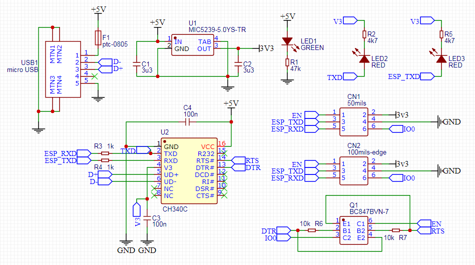
The schematics of the board are quite simple. The main part is the CH340C chip because programming an ESP32 automatically requires RTS and DTR pins. CH340T or G would also work, but they would require an external crystal. Then there is a usb port and a programming port. Additionally there is a fuse and place for an optional 3V3 regulator. The official ESP-Prog has a DIP switch to select whether the programmer should provide 3V3 or 5V voltage to the programming connector. I really don't want to use DIP switches however, so I've decided to just make fixed versions, with the regulator and without. If the regulator is installed, the connector will provide 3V3 to the device. If the regulator is not installed, the power pin of the connector will be floating, since I don't really see the need for 5V on the connector. Then there is the circuitry required to connect the RTS and DTR signals to the IO0 and ENABLE pins on the ESP32. Eventually I also decided to include the smaller 50mil connector on the board. It's location on the board is a little inconvenient, but it's there just in case, since the connectors are quite expensive and apparently not so easily available.

Last things are power and activity LEDs. The power led is connected directly to the 5V input. The activity LEDs are however connected to TxD and RxD signals, since there is no dedicated output for the activity LEDs in the CH340C chip. While connecting the LEDs it's important to note the polarity of the signals, since the UART signals are high when idle. This means that the other pin of each activity LED should be connected to the 3V3 voltage. The problem is that the 3V3 regulator is optional as stated above. For this reason I've connected the LEDs to the "V3" pin of the CH340 chip. This pin is the output of the internal 3V3 regulator and it's most definitely acceptable to connect low power LEDs to this pin. Lastly it's also important to choose proper resistors for the LEDs so they will not be too bright.


Creating the board is actually very simple. The idea is taken from any other Chinese made programming device. The board is a narrow strip. On one side is the USB port and the 6-pin IDC connector on the other. On top of the board is the CH340 chip and the dual transistor. On the bottom is the voltage regulator and that's basically it. The reason for such design is simple. The whole board can be encased in transparent heat shrink tube, which is quite neat in my opinion. This physically isolates the device (mostly) and makes the enclosure very slim (compared to any 3d-printed case). Also LEDs and PCB markings can be seen through the heat shrink tube. The only downside is that the PCB is a bit slimmer than the distance between the pins of the IDC connector so it often ends up slightly crooked, but I guess it's fine. I've acquired 12.7mm wide 2:1 heat shrink tube for this purpose and it works well in my opinion.


Result

At least I am completely satisfied with the result. The only problem with the assembly is hand-soldering the SOT363 cased dual transistor. The footprint is however large enough in my opinion, so that is not the problem here. I haven't used the programmer much yet, but for now it seems to function as well as the official ESP-Prog programmer. The final result is shown in the picture below. The public EasyEDA project can be found here.


Final words

One thing that I would really like to make is a proper light box. It would probably improve the quality of the pictures that I'm going to use in this blog. That is however a project for another time.

Note: As far as I know this programmer should also work for the ESP8266, but I haven't tried it.

Internet of Crosstrainers, part 2

Introduction As mentioned in the original post here , there were some issues in the described implementation. I had some difficulties to fin...