Introduction
I'm not going to explain here what ESP32 is in much detail. It is just some programmable module with WiFi capability. It can be programmed using the serial line and controlling few other pins of the module in a specific way. Originally I was programming these modules simply by entering programming mode by using buttons or just shorting the pins manually and then using some basic (CP2102 based) usb-serial adaptor. For some reason I was really against using a programmer. I really have no idea why. Later on I acquired an ESP-Prog programmer and would never go back to using buttons. This programmer however has some disadvantages that I really don't like. The biggest disadvantage is that this programmer does not have a case, so it's very easy to short something (yes, one could print a case using a 3d-printer, I don't have one). Lack of casing is not a problem by itself but usually the programmer is used with some kind of a development board or an incomplete project that also doesn't have a case. Having two devices without enclosure next to each other is already a serious risk. The other problem is that it's quite over-engineered and thus relatively large. Yes it does have JTAG support, but I haven't needed it yet and probably never will. There are also some switches included, both 50mil and 100mil IDC connectors and some other circuitry. Additionally there is a blue indicator light which in my opinion the worst choice for an indicator light. Don't get me wrong, I like bright and colorful lights.. but not as indicator lights. So I've decided to make a smaller version of this programmer using CH340C chip and encase it properly.
Electronics
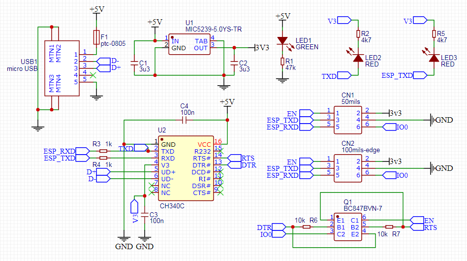
The schematics of the board are quite simple. The main part is the CH340C chip because programming an ESP32 automatically requires RTS and DTR pins. CH340T or G would also work, but they would require an external crystal. Then there is a usb port and a programming port. Additionally there is a fuse and place for an optional 3V3 regulator. The official ESP-Prog has a DIP switch to select whether the programmer should provide 3V3 or 5V voltage to the programming connector. I really don't want to use DIP switches however, so I've decided to just make fixed versions, with the regulator and without. If the regulator is installed, the connector will provide 3V3 to the device. If the regulator is not installed, the power pin of the connector will be floating, since I don't really see the need for 5V on the connector. Then there is the circuitry required to connect the RTS and DTR signals to the IO0 and ENABLE pins on the ESP32. Eventually I also decided to include the smaller 50mil connector on the board. It's location on the board is a little inconvenient, but it's there just in case, since the connectors are quite expensive and apparently not so easily available.
Last things are power and activity LEDs. The power led is connected directly to the 5V input. The activity LEDs are however connected to TxD and RxD signals, since there is no dedicated output for the activity LEDs in the CH340C chip. While connecting the LEDs it's important to note the polarity of the signals, since the UART signals are high when idle. This means that the other pin of each activity LED should be connected to the 3V3 voltage. The problem is that the 3V3 regulator is optional as stated above. For this reason I've connected the LEDs to the "V3" pin of the CH340 chip. This pin is the output of the internal 3V3 regulator and it's most definitely acceptable to connect low power LEDs to this pin. Lastly it's also important to choose proper resistors for the LEDs so they will not be too bright.
Creating the board is actually very simple. The idea is taken from any other Chinese made programming device. The board is a narrow strip. On one side is the USB port and the 6-pin IDC connector on the other. On top of the board is the CH340 chip and the dual transistor. On the bottom is the voltage regulator and that's basically it. The reason for such design is simple. The whole board can be encased in transparent heat shrink tube, which is quite neat in my opinion. This physically isolates the device (mostly) and makes the enclosure very slim (compared to any 3d-printed case). Also LEDs and PCB markings can be seen through the heat shrink tube. The only downside is that the PCB is a bit slimmer than the distance between the pins of the IDC connector so it often ends up slightly crooked, but I guess it's fine. I've acquired 12.7mm wide 2:1 heat shrink tube for this purpose and it works well in my opinion.

Result
At least I am completely satisfied with the result. The only problem with the assembly is hand-soldering the SOT363 cased dual transistor. The footprint is however large enough in my opinion, so that is not the problem here. I haven't used the programmer much yet, but for now it seems to function as well as the official ESP-Prog programmer. The final result is shown in the picture below. The public EasyEDA project can be found here.

Final words
One thing that I would really like to make is a proper light box. It would probably improve the quality of the pictures that I'm going to use in this blog. That is however a project for another time.
Note: As far as I know this programmer should also work for the ESP8266, but I haven't tried it.


No comments:
Post a Comment